


BIMINVERTSPACES command
Converts a set of input 3D solid entities and closed polylines, which represent spaces, to a building structure which encompasses these spaces.

Icon: 
Method
This command uses a set of 3D solid entities and closed polylines to create a building structure made of walls, openings, slabs, and roofs.
This command is envisioned to be most useful in a Scan-2-BIM workflow. Starting from a point cloud, using the FITPLANAR command to fit planar faces to the point cloud and stitch them together to solids (representing spaces) and finally using these solids as input for the BIMINVERTSPACES command.
The command takes closed polylines (created manually or with POINTCLOUDFITPLANAR command) into account and creates parametric opening components based on these polylines. The polylines do not need to be coplanar with a face (exactly on the face) of the space. When polylines are detected on both sides of the wall, the two polylines are interpolated and the opening is created based on the interpolation results. The parametric opening object can then easily be replaced with a window or door component, using the BMREPLACE command.
Launching the command opens the Invert Spaces command context panel to let you define the settings.
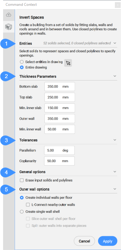
- Entities
- Thickness Parameters
- Tolerances
- General options
- Outer wall options
- Entities
- Displays the options for selecting the entities to be used as input.
- Select entities in the drawing
- Click on the arrow button to select specific 3D solids and closed polylines.
- Entire drawing
- All the 3D solids and closed polylines in the drawing will be used as input.
- Thickness Parameters
- Displays the values of the parameters used to create the building structure.
- Bottom slab
- Sets the thickness of the slabs created at the bottom of the structure.
- Top slab
- Sets the thickness of the slabs created at the top of the structure.
- Min. inner slab
- Sets the minimum distance required between parallel faces for creating an inner slab.
- Outer wall
- Sets the thickness of the walls created on the outside of the structure.
- Min. inner wall
- Sets the minimum distance required between parallel faces for creating an inner wall.
- Tolerances
- Displays the tolerance values for the relative positions of the faces that belong to the 3D solids used as input.Note: The units used by these settings are those set in the drawing.
- Parallelism
- Sets the angular tolerance for determining if the faces are parallel.
- Coplanarity
- Sets the allowed distance between the faces for being coplanar.
- General options
-
- Erase input solids and polylines
- On the completion of the command, the input entities are erased if the checkbox is ticked or kept if the checkbox is not ticked.
- Outer wall options
- Displays the options for creating the outer walls.
- Create individual walls per floor
- Creates separate outer walls for each floor. Outer walls are created by extruding coplanar groups of outer faces outward.
- L-connect nearby outer walls
- Creates mitered corner connections between nearby walls.
- Create single wall shell
- Creates the outer walls of the whole structure as a tight-fitting, single solid shell. Shelling may sometimes fail on non-aligned geometry.
- Slice outer wall shell per floor
- Divides the computed outer wall shell(s) to multiple 3D solids by slicing it by a horizontal plane at each floor level.
- Split outer walls in separate pieces
- Divides the computed outer wall shell(s) into smaller box-like 3D solids, one for each side of the structure.