Allows you to create a feature control frame symbol that can be attached to an entity in the drawing.
Note: The command can be launched only when using a Mechanical2d template file for the current drawing (JIS, ANSI, DIN and ISO standards).
Method
Select the entity to attach the edge symbol and specify the points for its location.
There are two use cases to activate the mechanical entities:
When creating a new drawing that contains mechanical entities:
Set the LOADMECHANICAL2D system variable to ON (1).
Start a new drawing using a Mechanical2d template.
When opening a drawing that contains mechanical entities:
Set the LOADMECHANICAL2D system variable to ON (1).
Open an existent ACM drawing and start special symbols creation.
Note: These dimensions are compatible with the legacy AutoCAD® Mechanical application.
Note: The dimensions will be added to the AM_5 layer.
Note: After opening a drawing that contains mechanical entities, filling other drawings with mechanical-related data will be done on-demand in contrast to previous versions. It will be possible when a user copies the mechanical-related entities to the vanilla drawing. In case of copying entities that are not related to the mechanical data, a vanilla drawing will not be filled with mechanical data.
Note: When you open a drawing that contains mechanical entities, but the LOADMECHANICAL2D system variable is OFF, a warning bubble is displayed at the status bar that describes the situation and provides a hyperlink to immediately enable and load the mechanical 2d modules.
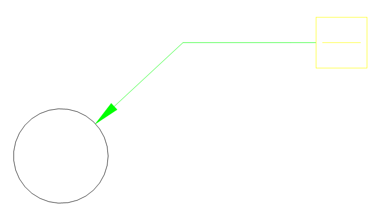
Select the entity to attach the feature control frame symbol to. Depending on the selected entity, you can select the start point or the second point of the feature control frame leader. If needed, add more points to the leader, then press Enter to end the command.
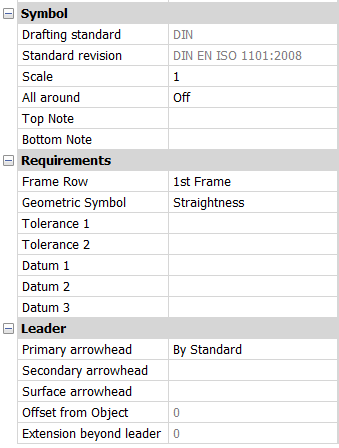
After creating the frame symbol with the AMFCFRAME command, their properties can be configured in the Properties panel:
Symbol
Drafting standard
Displays the drafting standard.
Standard revision
Displays the standard revision.
Scale
Sets the note scale.
All around
Toggles the visibility of the all around surface texture in the symbol.
Top Note
Inserts a note to add above the symbol.
Bottom Note
Inserts a note to add bellow the symbol.
Requirements
Defines the symbol requirements.
Frame row
Allows you to choose between 1st Frame or 2nd Frame.
Geometric Symbol
Allows you to choose a geometric symbol from the drop-down list.
Tolerance 1
Allows you to type in the tolerance to appear next to the geometric symbol.