ARRANGE command
Spatially organizes a set of entities by aligning and/or distributing them along the axes of the current UCS.

Methods
The ARRANGE command spatially organizes a set of entities (2D and/or 3D) by aligning and/or distributing them along the axes of the current UCS.
This command creates a new arrangement of the selected entities. The arrangement of the entities is defined based on the bounding boxes of the selected entities (i.e., the smallest box which contains the entity), with respect to the selection bounding box (i.e., the smallest box which contains all selected entities).
To make a new arrangement with the selected entities, the ARRANGE command uses the following elements:
- A selection of entities (these can be both 2D and 3D).
- A direction for the arrangement. This can be a main axis (X, Y, or Z) of the current UCS.
- The bounding box of the selection.
- The bounding boxes of each entity in the selection.
- The arrangement option selected by the user.
The workflow of the ARRANGE command includes the following steps:
- Launch the ARRANGE command.
- Select the entities to arrange. The entities can be both 2D and 3D.
- Choose a direction.Choose the UCS axis (X, Y, or Z) along which you want to arrange the entities. Entities will only be moved along this direction.
You can perform as many arrange operation as you want on the original set of entities with a single run of the command.
- Choose one of the 8 arrangement options of the command (see below).
- Return to step 3.
- (Optionally) Undo the arrangements step by step.Note: The UNDO option is available after an alignment option is applied.
- Select Finish or press Enter to finalize the command.
The arrangement of the selected entities is done with the following approach:
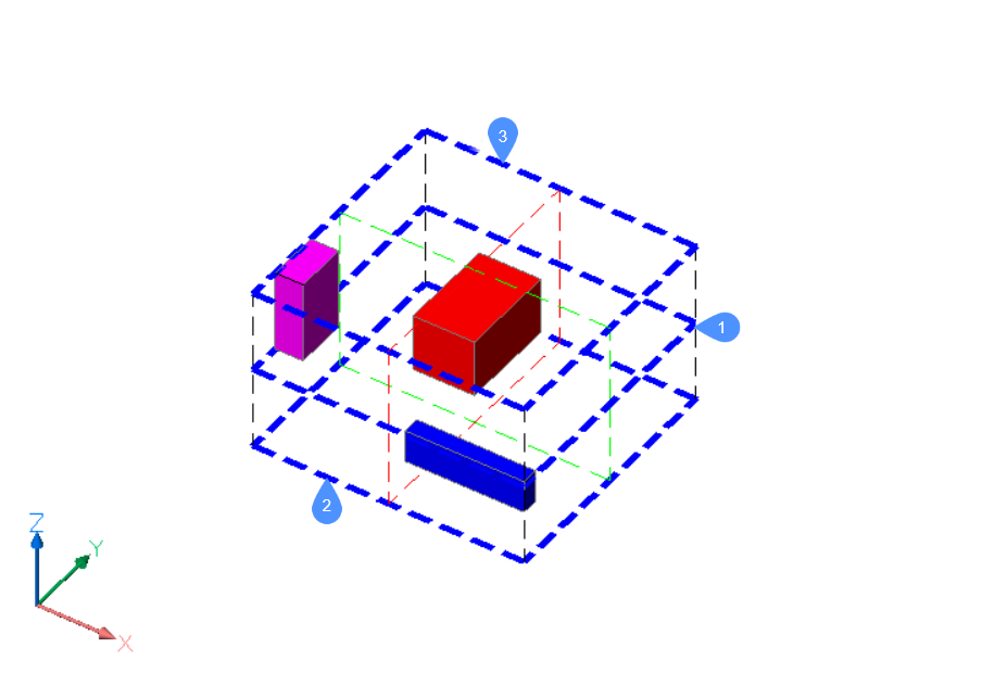
To create a new configuration of the selected entities, the ARRANGE command uses some bounds. First, there are the main bounds, that are attached to the selection bounding box. Then, there are the secondary bounds, that are attached to the bounding boxes of each entity in the selection.
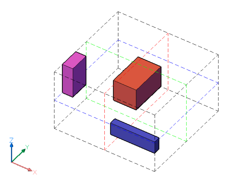
The selection bounding box is represented by black dashed lines. The bounds of the selection bounding box are defined by its six faces, two for each axis of the current UCS. There are also three center bounds, one for each axis, located in the center of the selection bounding box. The center bounds are represented by colored dashed lines, red for X axis, green for Y axis and blue for Z axis.
The colored boxes are the bounding boxes of the selected entities. For each entity in the selection, there are six outside bounds, defined by the faces, and three center bounds. The bounds of an entity are defined similarly to the ones of the selection bounding box.
In summary:
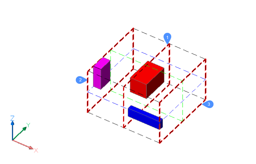
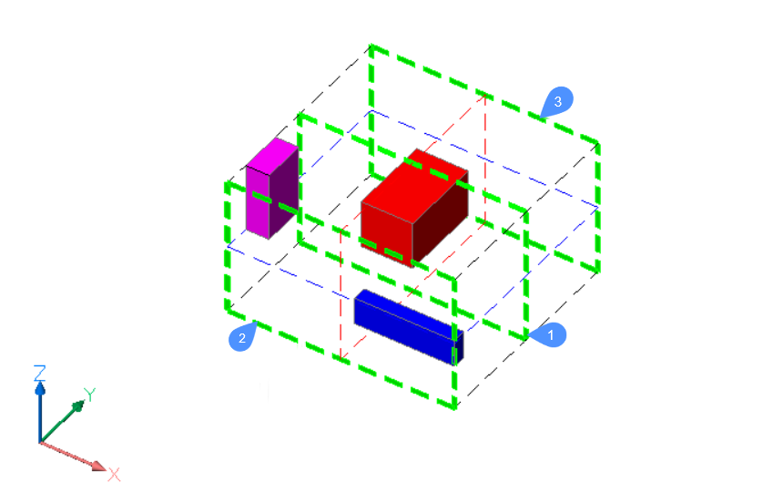
- The selection of entities has a total of nine bounds. There are three bounds for each of the axes of the UCS. The notation of these bounds are 1 (Center), 2 (Lower), and 3 (Upper), for each of the axes.
- Also, each entity has nine bounds, similar to the ones of the selection.
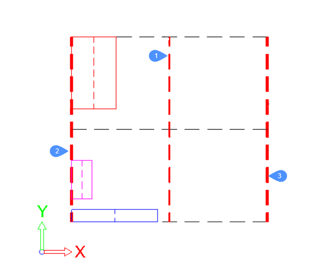
For each axis, the bounds are defined as follows:
2 - the Lower bound is defined by the face of the bounding box placed at the smallest coordinate along the specified axis.
3 - the Upper bound is defined by the face of the bounding box placed at the largest coordinate along the specified axis.
1 - the Center bound is located between the 2 (Lower) and 3 (Upper) bounds at the same distance from each of them.
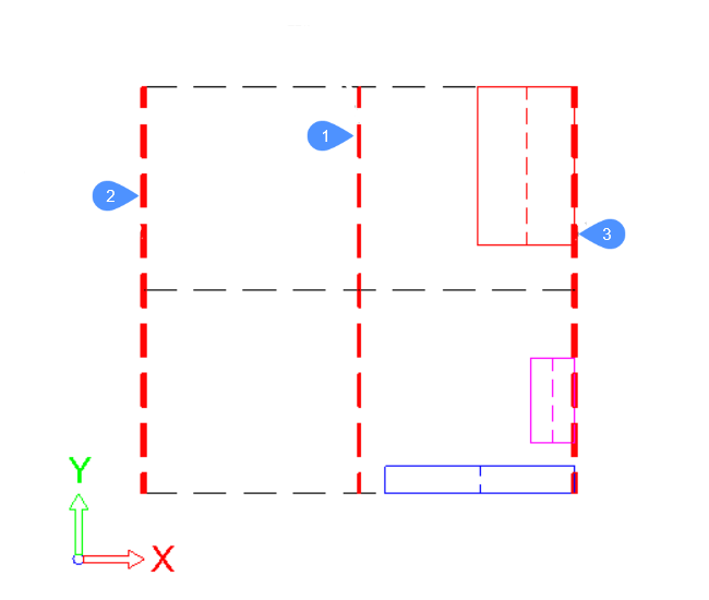
In the pictures below, the bounds of the selection bounding box are highlighted with thick dashed lines.
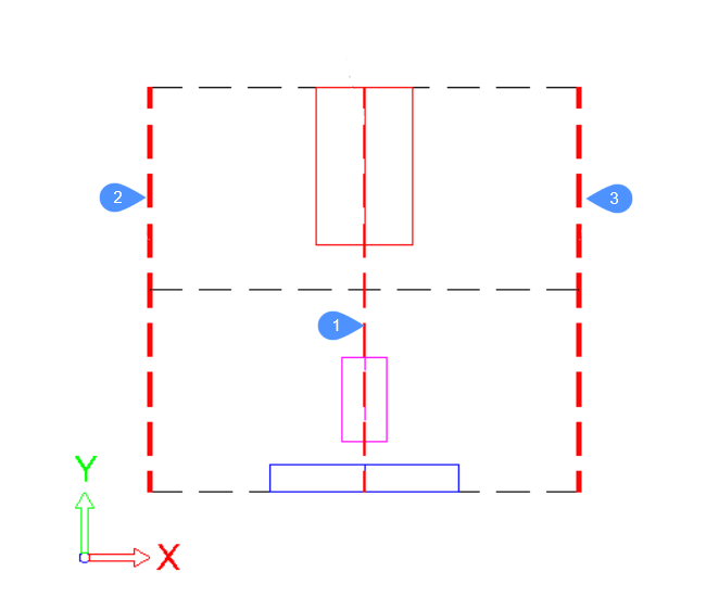
To define the new position of an entity in the selection, the ARRANGE command uses the bounds of the selection, the bounds of the entity, and the method selected by the user.
Options within the command
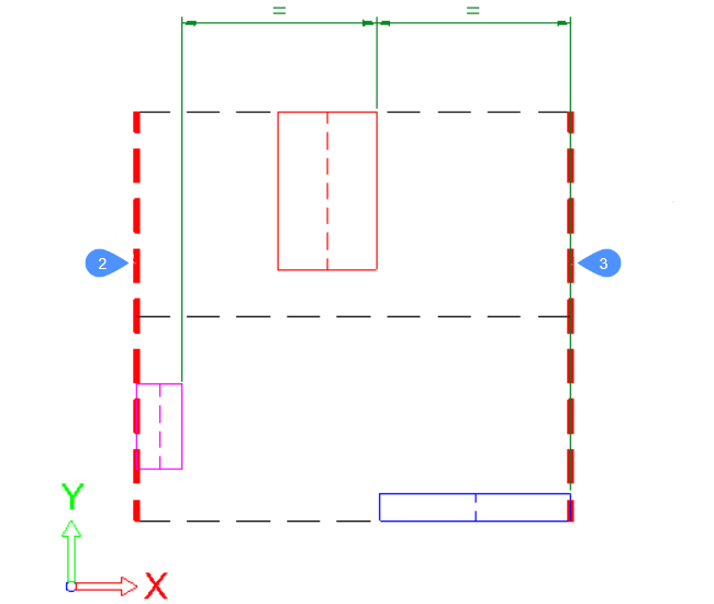
In this example, the arrangement will be made by using X as direction.
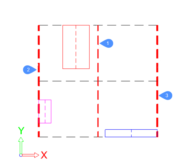
The main bounds, attached to the selection bounding box, are represented by thick dashed red lines.
For each entity in the selection, its bounding box is represented by continuous lines, each with a different color. In this case, for each entity, the bounds, 2 (Lower), 1 (Center) and 3 (Upper), will be the left side, center line and right side of its bounding rectangle, respectively.
For the red entity, the bounds will be like this:

For the other entities, the bounds are defined in a similar way.
- None
- The entities will not be arranged along the specified direction. If an arrangement was already set along the specified direction during the execution of the command, the entity will be moved to its original position on the specified axis.
- Lower Align
- The lower bound of each entity will be aligned with the lower bound of
the selection bounding box in the specified direction.
- Center Align
- The center bound of each entity will be aligned with the center bound of
the selection bounding box in the specified direction.
- Upper Align
-
The lower bound of each entity will be aligned with the lower bound of the selection bounding box in the specified direction.
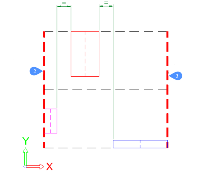
- Equally spaced
- The gaps between the entities will have the same size along the
specified direction.
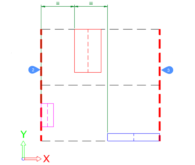
- Lower Equally spaced
- The distance between the lower bounds of consecutive entities will be
the same along the specified direction.
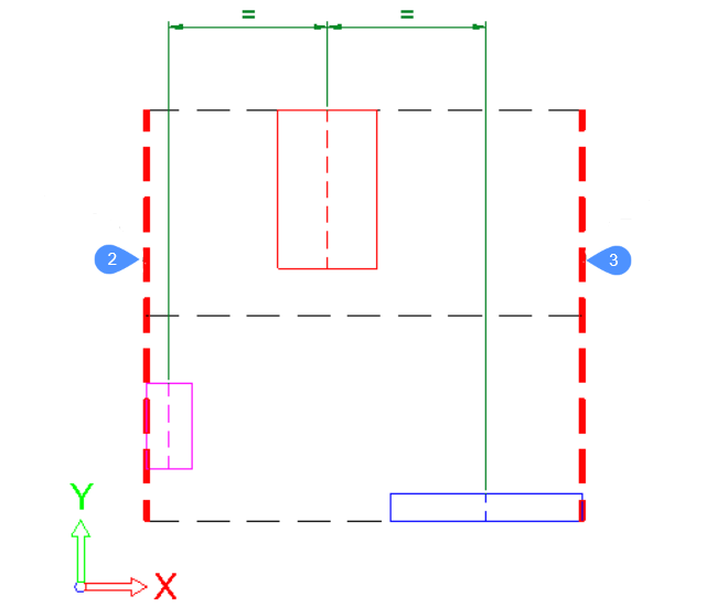
- Center Equally spaced
- The distance between the center bounds of consecutive entities will be
the same along the specified direction.
- Upper Equally spaced
- The distance between the lower bounds of consecutive entities will be
the same along the specified direction.