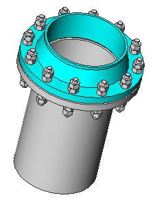
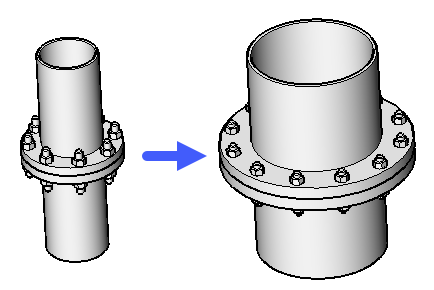
Connette due componenti mediante la creazione di vincoli 3D tra le relative entità di connessione. Inoltre, nell'opzione Assemblaggio completo della flangia, una guarnizione e un assieme di bullonatura vengono inseriti, ridimensionati e collegati a una coppia di flange.
Icona:
Metodo
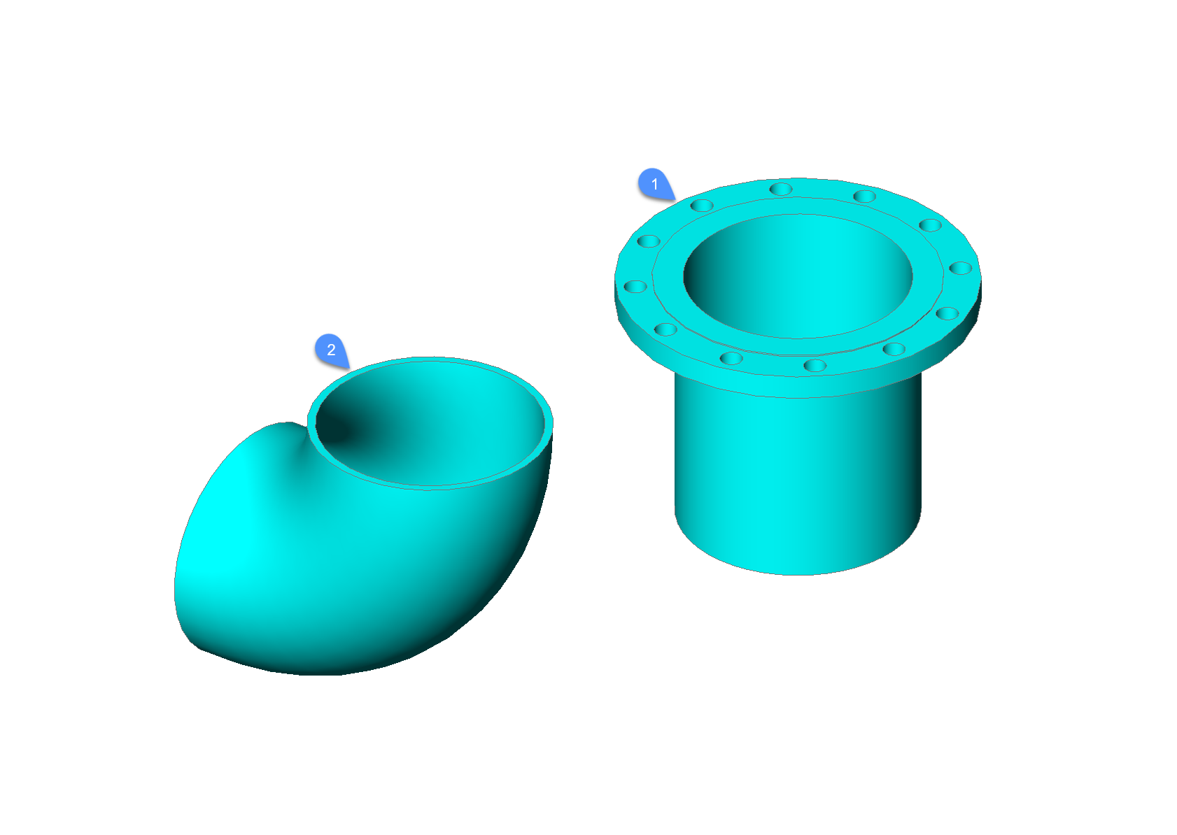
Selezionare i componenti da collegare
Selezionare il componente da collegare. (1)
Selezionare il componente di destinazione
Selezionare il componente a cui connettersi. (2)
Note: Sono accettati anche i blocchi meccanici.
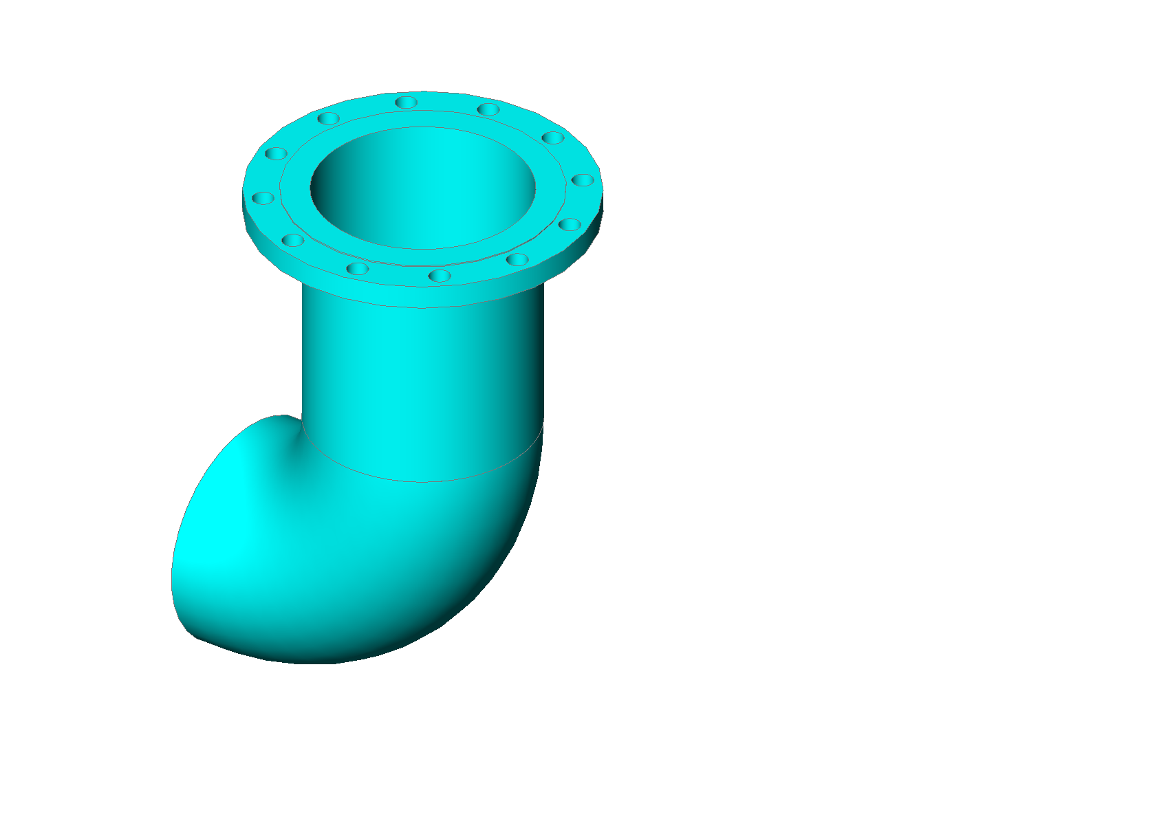
Il comando crea automaticamente una serie di vincoli 3D per collegare correttamente le parti e mantenere la loro posizione relativa per qualsiasi ulteriore modifica.
Opzioni all'interno del comando
Inverti
Per il componente (1) viene selezionata la coppia successiva di punto di connessione e linea
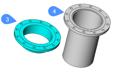
Assemblaggio completo della flangia
È possibile selezionare una guarnizione e un gruppo di bullonatura per collegare automaticamente le flange (3) e (4).
Se i parametri Size e Rating dell'assieme di bullonatura delle flange, delle guarnizioni e dell'assieme di bullonatura sono collegati ai parametri globali Size e Rating, l'assieme flangia verrà aggiornato correttamente quando questi parametri globali vengono modificati.
Guarnizione
Permette di scegliere una guarnizione per il gruppo flangia.
elenco delle guarnizioni disponibili (?)
Elenca tutte le guarnizioni disponibili nella barra dei comandi.
Percorso
Consente di scegliere una guarnizione personalizzata dalla finestra di dialogo Seleziona un file di guarnizione (Finestra di Dialogo Standard).
PUlisci
Rimuove la guarnizione scelta.
assemblaggio di Bulloni
Seleziona un assieme di bullonatura.
Note: La bullonatura è un assemblaggio parametrico di elementi di fissaggio per una coppia di fori di bullonatura delle flange, ad esempio un perno e 4 dadi. Tutti i dadi sono dello stesso tipo. Due di questi dadi possono essere soppressi, in base al parametro NutsNumber.
Note: L'assieme bulloneria è un assieme parametrico che contiene una serie polare di bulloni (ed entità 2D di connessione). I parametri Dimensione e Valutazione possono essere collegati ai parametri globali corrispondenti.
Note: L'assemblaggio flangia è un assieme della coppia collegata di flange, guarnizione e assieme bullone.
Percorso
Consente di scegliere un assieme di bullonatura esistente dalla finestra di dialogo Seleziona un file di assieme di bulloli (Finestra di Dialogo Standard).
Genera
Genera un assieme di bullonatura da una bullonatura.
Percorso
Consente di scegliere una bullonatura esistente dalla finestra di dialogo Selezionare un file di bullonatura (Finestra di Dialogo Standard).
Genera
Genera una bullonatura.
Selezionare un perno
elenco perni disponibili (?)
Elenca tutti i perni disponibili nella barra dei comandi.
Percorso
Consente di scegliere un perno personalizzato dalla finestra di dialogo Seleziona un file di perni (Finestra di Dialogo Standard).
Selezionare un dado
elenco dadi disponibili (?)
Elenca tutti i dadi disponibili nella barra dei comandi
Percorso
Consente di scegliere un dado personalizzato dalla finestra di dialogo Seleziona un file di dadi (Finestra di Dialogo Standard).
Specificare il nome del bullone
Assegna un nome alla bullonatura generata in precedenza e la salva nella finestra di dialogo Seleziona il file di bullonatura.
Specificare il nome dell'assieme bullone
Assegna un nome alla bullonatura generata sopra e lo salva nella finestra di dialogo Seleziona il file di bullonatura.
Conserva il file di bullonatura
Specifica se mantenere il file di bullonatura
Selezionare il numero di dadi
Specifica il numero di dadi.
Incremento della lunghezza di input
Specifica l'incremento di lunghezza del perno.
Auto
Applica il perno, dado, incremento di lunghezza, numero di dadi per l'assieme di bullonatura.
Viene generato e scelto un assieme di bullonatura temporaneo. Il suo file verrà rimosso al termine dell'esecuzione del comando.
PUlisci
Rimuove l'assieme di bullonatura scelto.
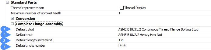
IMpostazioni
Apre la finestra di dialogo Impostazione:
BoltingAsmDefaultStud - perno predefinito per generare l'assieme di bullonatura.
BoltingAsmDefaultNut - dado predefinito per generare l'assieme di bullonatura.
BoltingAsmDefaultLengthIncrement - incremento predefinito lunghezza per il perno predefinito.
BoltingAsmDefaultNutsNumber - numero dadi predefinito per l'assieme di bullonatura.
Indietro
Ritorna alla precedente opzione della barra dei comandi.
Fine
Crea l'assieme di flange, guarnizione e gruppo bullonatura.