


RAY command
Creates rays.

Icon: 
Description
Creates a ray (semi-infinite line) from a combination of options including point, direction and angle.
- Start of ray
- Direction
Methods to begin a ray
This command has 6 methods to begin creating a ray:
- Start of ray
- Horizontal
- Vertical
- Angle
- Bisect
- Parallel
You can continue adding unlimited rays until you press Enter to end the command.
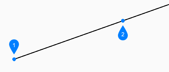
- Start of ray
- Begin creating a ray by specifying the starting point of the ray then:
- Direction
- Specify the direction of the ray from the starting point.
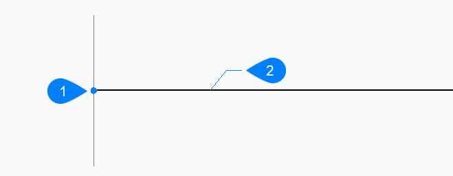
- Horizontal
- Begin creating a ray horizontal to the x-axis then:
- Location
- Specify the starting point of the ray.
- Vertical
- Begin creating a ray parallel to the y-axis then:
- Location
- Specify the starting point of the ray.
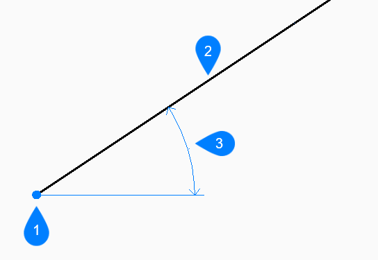
- Angle
- Begin creating a ray based on an angle then:
- Enter angle
- Specify the angle of the ray.
- Location
- Specify the starting point of the ray.
- Location
- Ray
- Angle
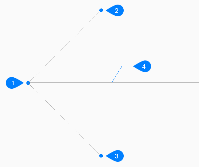
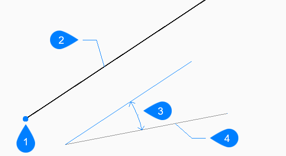
- Bisect
- Begin creating a ray which bisects the angle between two imaginary lines then:
- Set vertex point
- Specify the start point of the ray.
- Bisection angle start point
- Specify a point to define the first imaginary line. The vertex is used as the other point.
- Bisection angle end point
- Specify a point to define the second imaginary
line. The vertex is used as the other point.
- Vertex point
- Bisection angle start point
- Bisection angle end point
- Ray
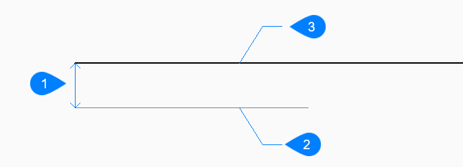
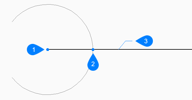
- Parallel
- Begin creating a ray parallel to a line or polyline segment then:
- Set offset distance for parallel infinite ray
- Specify the offset distance for the ray.
- Select entity for parallel infinite ray
- Select a line or polyline segment from which to offset the ray.
- Side for parallel infinite ray
- Specify the side on which to place the ray. The
ray’s start point is parallel to the line’s start point.
- Offset distance
- Line segment
- Ray
Options within the RAY command
After you begin creating a ray, the following options may be available:
- Reference
- Select an entity to use a reference angle then:
- Enter angle
-
Specify the angle to place the ray relative to the selected entity.
- Location
- Specify the starting point of the ray.
- Location
- The Location prompt repeats
so that you can draw more angled rays with different starting points.
Press Enter to end the command.
- Location
- Ray
- Angle
- Reference entity
- Entity
- Select a line, arc, a polyline segment to bisect then:
- Select side for ray bisection
- Specify the side on which to place the ray.
- This command works with splined polylines, but not
with splined entities.
- Perpendicular to arc center point
- Perpendicular to arc midpoint
- Ray
- Perpendicular to line midpoint
- Ray
- Through point
- Specify a point through which to draw the ray.
- Select entity for parallel infinite ray
- Specify the entity to offset with the ray.
- Through the point
- Specify the point through which to draw the ray.
This point is the ray’s start point.

- Through point
- Line segment
- Ray