


CURVEDIRIFERIMENTO
Crea una geometria di riferimento per allineare automaticamente un blocco durante l'inserimento.

Icona: 
Metodo
Le entità selezionate che si desidera utilizzare come riferimento per allineare il blocco inserito verranno spostate in un nuovo layer REFERENCE_CURVES creato (se non esiste già).
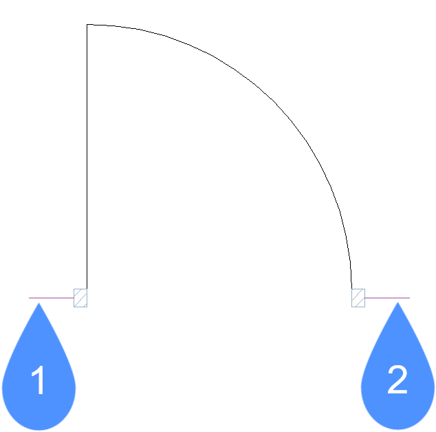
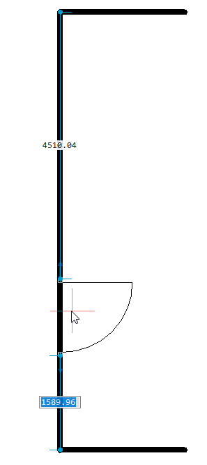
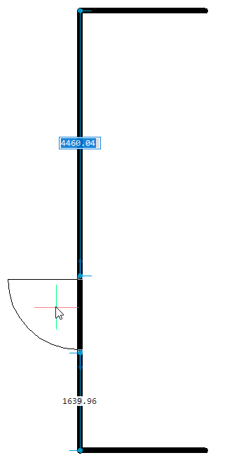
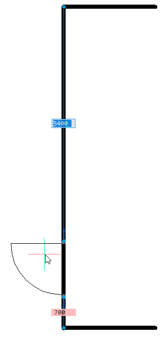
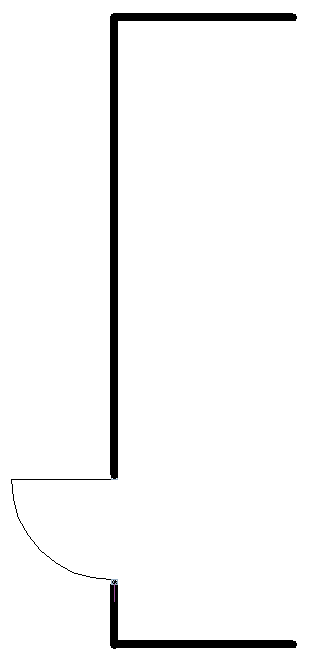
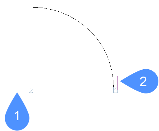
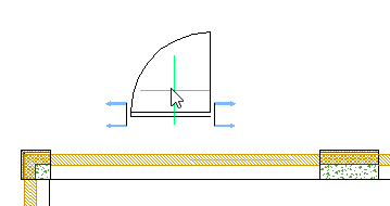
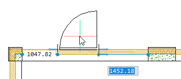
Con curve di riferimento ((1) e (2)) specificate in un disegno o in una definizione di blocco, è possibile allineare automaticamente il blocco o il disegno alla geometria pertinente quando lo si inserisce. Il numero di curve di riferimento e la distanza tra di esse determina la geometria che può allineare. Quando il cursore si avvicina alla geometria pertinente, il blocco si capovolge automaticamente, offrendo più opzioni di inserimento. Vengono visualizzate le distanze tra le estremità della geometria pertinente e del blocco, consentendo di immettere valori specifici, se lo si desidera. Inoltre, se le curve di riferimento includono spazi vuoti, la geometria pertinente viene automaticamente tagliata per produrre spazi corrispondenti.
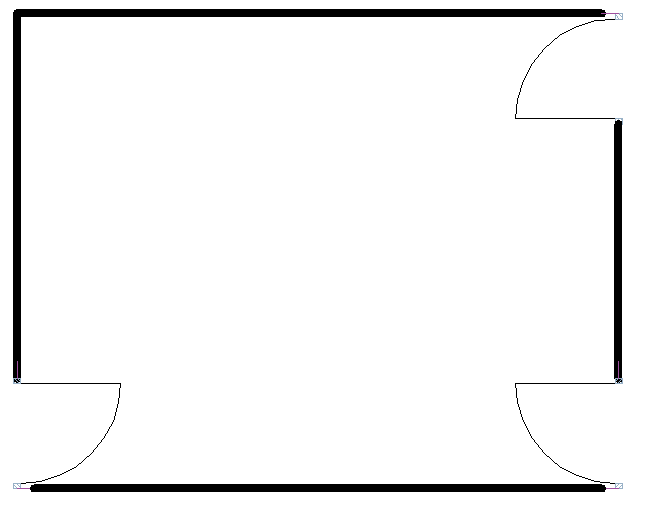
È possibile anche utilizzare le curve di riferimento per allinearsi automaticamente con gli angoli. L'esempio seguente include una curva di riferimento parallela (1) e una curva di riferimento ad angolo (2) che consente al blocco porta di allinearsi con la geometria che corrisponde alla linea parallela e alla linea perpendicolare.
Opzioni
- Parametrizza
- Parametrizza le curve di riferimento, in modo che il blocco parametrico risultante possa essere inserito in modalità "indefinito". Ad esempio, è possibile parametrizzare le quattro curve di riferimento parallele in un semplice esempio di porta. Successivamente è possibile inserire in modo guidato il blocco porta parametrico risultante in pareti con spessori diversi.
- Accetta
- Crea curve di riferimento senza parametrizzare.