Creates an xline (infinitely long line) from a combination of options point,
direction, and angle.
Point along line
Direction
Methods to begin an xline
This command has 6 methods to begin creating an xline:
Set point along line
Horizontal
Vertical
Angle
Bisect
Parallel
You can continue adding unlimited xlines until you press Enter to end
the command.
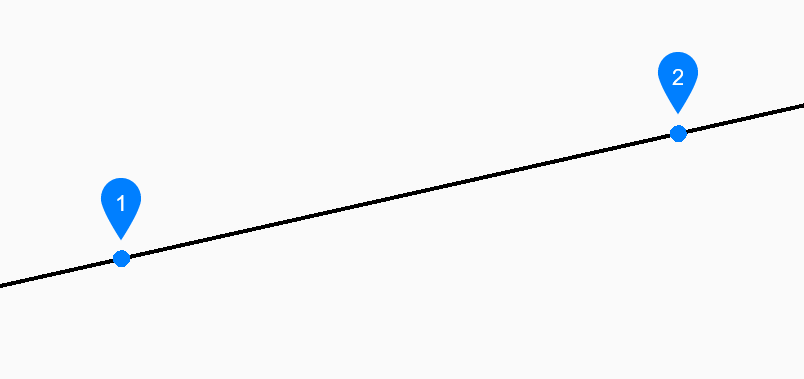
Set point along line
Begin creating an xline by specifying a point on the xline then:
Direction
Specify the direction of the xline from the
starting point.
Horizontal
Begin creating an xline parallel to the x-axis then:
Location
Specify a point on the xline.
Vertical
Begin creating an xline parallel to the y-axis then:
Location
Specify a point on the xline.
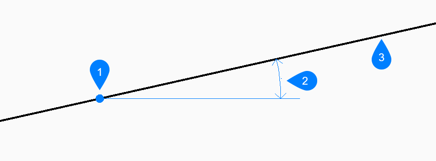
Angle
Begin creating an xline based on an angle then:
Enter angle
Specify the angle of the xline.
Additional option: [Reference]
Location
Specify a point on the xline.
Location
Angle
Xline
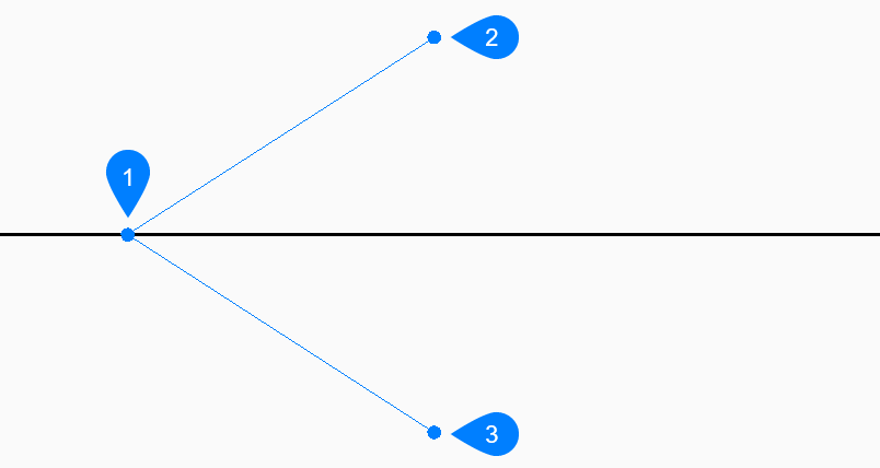
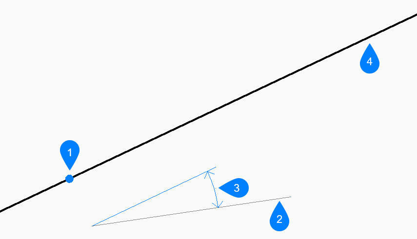
Bisect
Begin creating an xline which bisects two imaginary lines then:
Set vertex point
Specify a point at the vertex of the two imaginary
lines.
Additional option: [Entity]
Bisection angle start point
Specify a point to define the first imaginary
line. The vertex is used as the other point.
Bisection angle end point
Specify a point to define the second imaginary
line. The vertex is used as the other point.
Vertex point
Bisection angle start point
Bisection angle end point
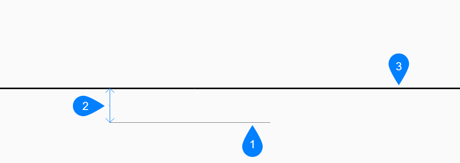
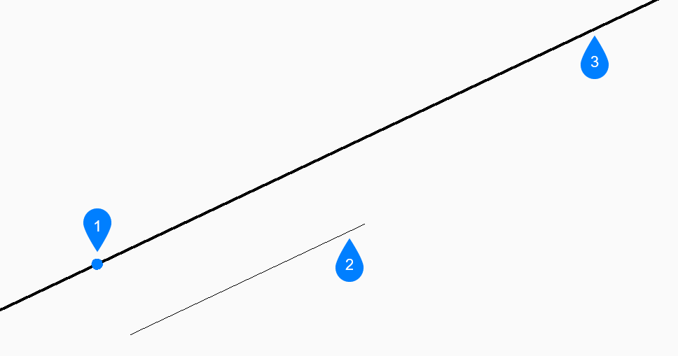
Parallel
Begin creating an xline parallel to a line or polyline segment then:
Set offset distance for parallel infinite line
Specify the offset distance for the xline.
Additional option: [Through point]
Select entity for parallel infinite line
Select a line or polyline segment from which to
offset the xline.
Side for parallel infinite line
Specify the side on which to place the xline.
Line segment
Offset distance
Xline
Options within the XLINE command
After you begin creating an xline, the following option may be available:
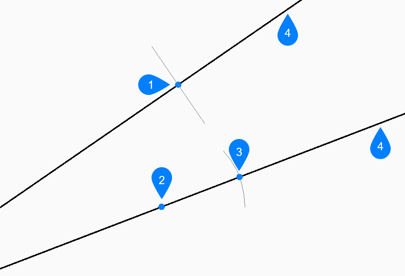
Reference
Select an entity to use as a reference angle then:
Enter angle
Specify the angle to place the xline relative to
the selected entity.
Location
Reference entity
Angle
Xline
Entity
Select a line, arc or polyline segment to bisect. When you select a line
or polyline segment, the command draws the xline perpendicular to the
segment’s midpoint. When you select an arc or polyarc, the command draws
the xline perpendicular to the arc’s center and point.
This option works with splined polylines, but not with spline entities.
Perpendicular to line's midpoint
Perpendicular to arc's centerpoint
Perependicular to arc' midpoint
Xline
Through point
Specify a point through which to draw the xline
Select entity for parallel infinite line
Select an entity to which the xline should be
parallel.