


Insert block dialog box
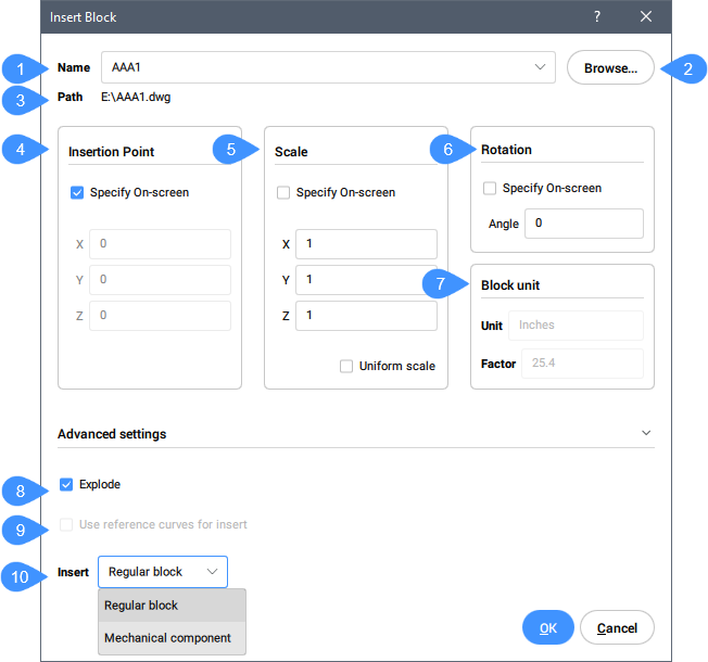
The Insert Block dialog box allows you to insert parametric blocks into the current drawing. You can also insert entire DWG and DXF files as blocks into the drawing.
- Name
- Browse
- Path
- Insertion Point
- Scale
- Rotation
- Block unit
- Explode
- Guided Insert
- Insert mode
Name
Specifies the name of the block, whose definition exists in the drawing, or is a DWG or DXF file on the computer or network.
Browse
Selects a DWG or DXF file from your computer or network. Opens the Select Drawing File dialog box.
Path
Displays the path to the block, if the block was opened from a DWG or DXF file.
Insertion Point
Specifies the insertion point of the block in the drawing.
Scale
Scales the block:
- X, Y, Z: Defines the scaling of the block:
- X specifies the scale factor along the x axis. Enter a negative value to mirror the block about the y axis.
- Y specifies the scale factor along the y axis. Enter a negative value to mirror the block about the x axis.
- Z specifies the scale factor along the z axis.
- Uniform Scale: Toggles whether the same scale factor is used for all axes.
- Values larger than 1 make the block larger.
- 1 inserts the block at actual size.
- Values smaller than 1 make the block smaller.
- Values less than zero flip the block, like mirroring it.
Rotation
Specifies the rotation angle of the block about its insertion point, starting with the x-axis as 0 degrees.
Block unit
Controls the automatic scaling of the block with respect to the INSUNITS system variable of the current drawing.
Explode
Toggles whether the block is inserted exploded.
Guided Insert
When the selected dwg contains guide curves, the Use reference curve for insert option becomes selectable. Specifies whether a reference curves should be used for insert or not.
Insert mode
If INSMODEAUTO setting is enabled insertion mode is determined automatically depending on block that user tries to insert. There are two insertion block modes:
- Regular block
- Inserts the block as a regular block.
Command line options
- Edit inserted entity
- Enables you to change the parameter expressions for the inserted entity. Continue editing individual parameters until you press Enter to end the option. This option is also available in the Hot Key Assistant.
- Enter the parameter name or press ENTER to finish
- Specifies the name of the parameter.
- Enter expression
- Specifies the expression for the parameter.
- Rotate component
- Allows you to change the rotation angle for the inserted entity.
- Rotation angle for block
- Specifies the rotation angle.
- set Base point
- Allows you to change the basepoint for the inserted entity.
- New base point <0,0,0>
- Specifies a new base point for the entity.
- Flip
- Allows you to flip the direction for the inserted entity.
- Multiple
- Allows you to insert multiple copies of the same entity by specifying an insertion point for each instance or creating an Array.
- Select insertion point
- Specifies a point in the current drawing where the entity will be inserted. Continue inserting entities until you press Enter to end the command.
- Array
- Allows you to create an associative array of the inserted entity.
- Specify base point for linear array
- Specifies a point.
- Enter the distance between columns
- Specifies the distance between columns.
- Enter the distance between rows
- Additional options: [Single row/Rectangular/Direction]
- Select an end point for creating array
- Specifies a point.
- Accept resulting array
- Press Enter to accept the array.
- Scale
- Allows you to scales the inserted block.
- Scale factor for block
- Specifies the scale factor.
- X scale
- Allows you to scales the inserted block on X axis.
- X scale factor for block
- Specifies the X scale factor.
- Y scale
- Allows you to scales the inserted block on X axis.
- Y scale factor for block
- Specifies the Y scale factor.
- Z scale
- Allows you to scales the inserted block on X axis.
- Z scale factor for block
- Specifies the Z scale factor.
- Mechanical component
- Inserts the block as a mechanical block if MECHANICALBLOCKS setting is enabled otherwise inserts the block as a mechanical component.
- Name
- Allows you to change the instance name for the inserted entity.
- Component insert name <DefaultName>
- Enters a name for the inserted entity.
- Change target 3d solids
- Allows you to apply the inserted entity to existing 3D solids in the current drawing.
- Select target 3D solids
- Selects the target 3D solids.
- Select all affected 3d solids
- All solids intersecting or touching solids in the BC_SUBTRACT and BC_UNITE layers of the inserted entity are affected.
- Clear
- Clears the selection set to ensure no solids are affected by the inserted entity.
- SMART insert
- Enables you to connect a Piping standard part to an existing Piping standard part. It automatically creates appropriate 3D constraints between the two parts and copies expressions for the parameters of the existing part to the new part. This option is also available in the Hot Key Assistant.
- Select entity to insert to or
- Hover the cursor over the Piping standard part you want to connect to.