


Weld Symbol dialog box
The Weld Symbol dialog box allows you to create specified weld symbols. It can be accessed using the AMWELDSYM command. The dialog box contains 2 main tabs:
- Symbol
- Leader and text
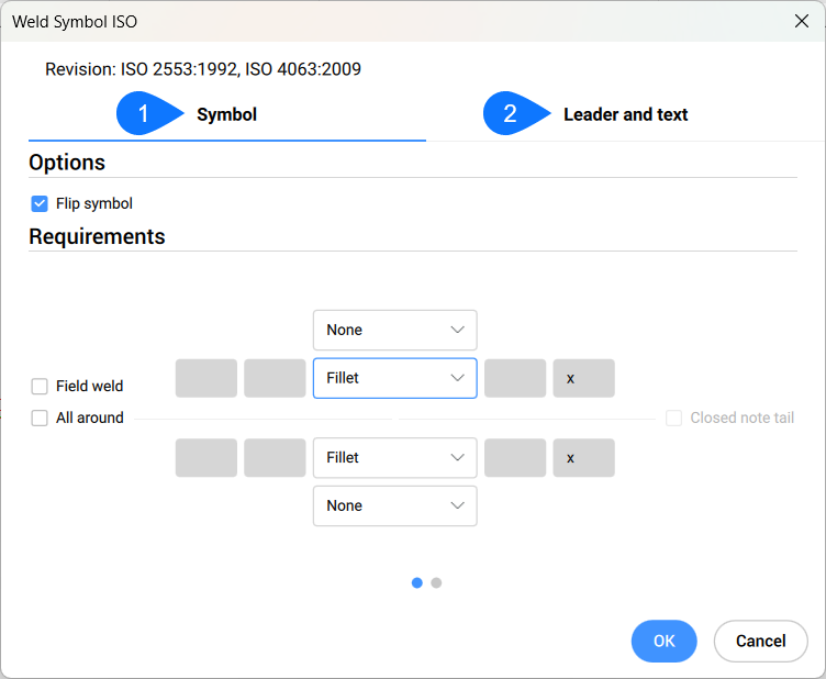
Symbol
Specifies the weld symbol characteristics.
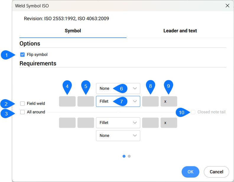
- Options
-
- 1. Flip symbol
- Specifies whether the symbol is aligned to the right or left.
- Not ticked: aligned to the right.
- Ticked: aligned to the left.
- Requirements
-
- 2. Field weld
- Toggle the visibility of the Field weld symbol in the welding symbol.
- 3. All Around
- Toggles the visibility of the All Around symbol in the welding symbol.
- 4. Depth
- Defines the groove depth of the weld.
- 5. Size
- Defines the size of the weld.
- 6. Contour
- Defines the shape of the weld from the below list:
- Concave Contour
- Convex Contour
- Flat/Flush Contour
- Flush Finished Contour
- Toes Shall Be Blended Smoothly
- None
- 7. Weld type
- Defines the weld type from the below options:
- Resistance spot (projection weld in system A)
- Fusion seam
- Resistance seam
- Backing Run; Back or Backing Weld / USA
- Flanged butt/corner
- Square butt
- V Butt
- Bevel butt
- U Butt
- J Butt
- Edge
- Fold Joint
- Inclined Joint
- Surface Joint
- Steep flanked V butt
- Steep flanked bevel butt
- V butt with broad root face
- Bevel butt with broad root face
- 8. Number
- Defines the number of welds.
- 9. Length
- Defines the length of the weld.
- 10. Closed note tail
- Displays a closed state of the note tail.
Leader and text
Specifies the Leader and text characteristics.
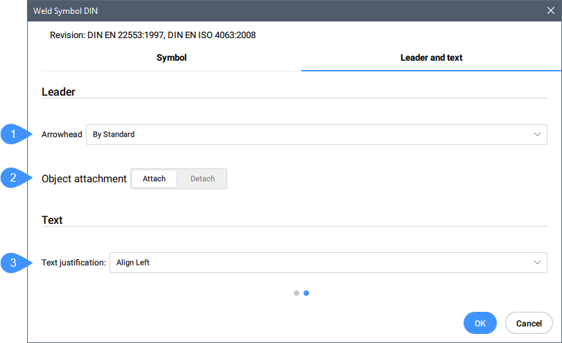
- Leader
-
- 1. Arrowhead
- Defines the default arrowhead type for welding symbols.
- 2. Object attachment
- Defines if the symbol leader is attached or detached to the object.
- Attach
- Attaches the symbol to the selected object.
- Detach
- Detaches the symbol from the object.
- Text
-
- 3. Text justification
- Specifies whether the symbol text is aligned to the right, center or left.