


Design intent recognition
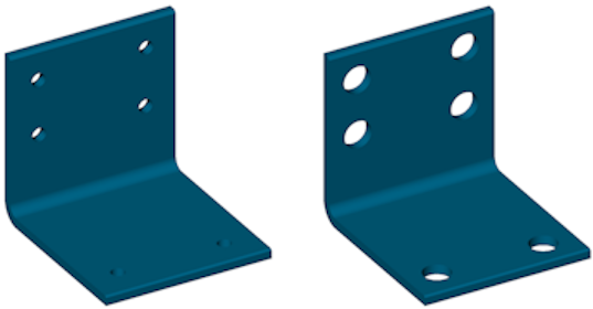
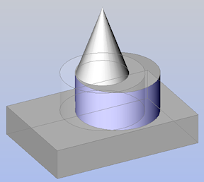
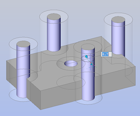
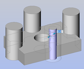
Direct modeling operations allow you to change geometry of 3D solid models easily: when a single face of a solid is modified with a particular operation other faces are modified accordingly in order to keep design intent of the model and its topological and geometrical validity. For example, consider a model with a number of holes of the same radius. When the radius of a cylindrical face is modified with a push/pull operation or by changing the value of a radial constraint other faces that share the same diameter are recognized by BricsCAD and modified automatically to keep the radii synchronized.
Apart from the recognition of equal radii, BricsCAD automatically recognizes other geometrical relations between surfaces of a solid and preserves them during direct modeling operations.
To define the design intent recognition, click the buttons on the Design Intent toolbar. A pressed button indicates the feature is selected. An unpressed button indicates the feature is not active.
- tangent surfaces (planes, cylinders and cones) (
 )
) - coincident planes (
 )
) - parallel planes (
 )
) - perpendicular planes (
 )
) - cylinders perpendicular to planes (
 )
) - coaxial surfaces (cylinders and cones) (
 )
) - surfaces of equal radius (cylinders and spheres) (
 )
) - vertices between 4 or more faces (
 )
) - edges between coincident faces (
 )
) - switch off/on all (
 )
)
The design intent options can also be set by editing the DMRECOGNIZE system variable in the Settings dialog box.
Click the Options tool button ( ) on the 3D Constraints toolbar to set the Automatic 3D geometry constraints recognition. The state of tool buttons on the Design Intent toolbar (pressed or unpressed) is adjusted accordingly.
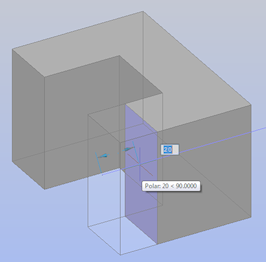
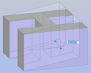
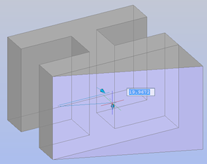
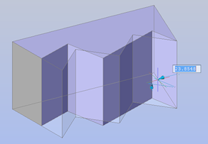
The following examples illustrate the difference in the behavior whether automatic 3D geometry constraints are recognized or not.
|
|
| tangent surfaces recognized ( |
tangent surfaces not recognized () |
|
|
| coincident plane recognized ( |
coincident planes not recognized () |
|
|
| parallel planes recognized ( |
parallel planes not recognized () |
|
|
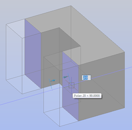
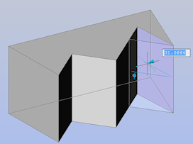
| perpendicular planes recognized ( |
perpendicular planes not recognized () |
|
|
| perpendicular cylinders recognized ( |
perpendicular cylinders not recognized () |
|
|
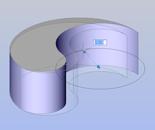
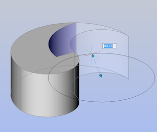
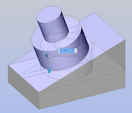
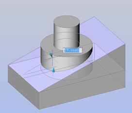
| coaxial surfaces recognized ( |
coaxial surfaces not recognized () |
|
|
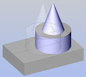
| equal radius recognized ( |
equal radius not recognized () |