


Components and component inserts
A component is a named group of entities, that can be inserted in a drawing with the BmInsert command. Components can be parametric: e.g. windows and doors, in BricsCAD BIM and standard mechanical components in BricsCAD Mechanical.
Any .dwg file can be used as a component. The same component can be inserted once or several times into one or more other components. When the component is modified, all inserts of the component will reflect these changes automatically. Components cannot self-reference.
A component insert is a named entity. The default name of a component insert is composed of the name of the component and the serial number of the insert. Internally a component insert is represented either as a reference to an anonymous block or as an external reference.
Properties of inserted components, including their parameters, can be edited in the Mechanical Browser panel and Properties panel.
External and local components
Components can be either local or external. A local component is stored in the .dwg file with the assembly as an anonymous block. An external component is defined in a separate .dwg file and represented by an Xref or as a local copy stored as an anonymous block. When the corresponding .dwg file is modified all inserts of external components can be updated using the BMUPDATE command or the Mechanical Browser context menu. If you use external components in your assembly, always remember to transfer all related files when you want to share your model.
Use the ETRANSMIT command to create a package of a drawing file and all its dependencies, such as external references, images, font files, plot configuration files, plot style tables and font map files.
You can always convert a local component to an external one and vice versa.
To edit a local component, it first needs to be converted to an external component using the BMEXTERNALIZE command. Alternatively, you can use the BMOPENCOPY command to open a copy of a component, edit and save it. Then use the BMREPLACE command to replace the original with the copy.
You can choose the default insertion type for your component: Local or External. To change the type, select the root node in the Mechanical Browser and select Local or External from Insert as properties.
Depending on the value of BMAUTOUPDATE, inserts of external components are updated automatically on opening the assembly document or manually with the BMUPDATE command. You can change this value in the Settings dialog box. The options are:
- Update only when the BMUPDATE command is used.
- Update automatically upon opening the file.
Converting components
The BMEXTERNALIZE command converts local components to external components.
The BMLOCALIZE command converts external components to local components.
Do one of the following:
- Click Switch Component to External (
 ) or
Switch Component to Local on the
Assembly ribbon tab. The tools are also available
from the Assembly toolbar and the
Assembly menu.
) or
Switch Component to Local on the
Assembly ribbon tab. The tools are also available
from the Assembly toolbar and the
Assembly menu. - Right-click on the component insert in the Mechanical Browser and select Switch to External or Switch to Local in the context menu.
- Hover your mouse cursor over a component insert in a drawing window and select
Switch to External () or
Switch to Local in the Assembly Modeling
command group in the Quad.
When you convert an external component to a local one, the .dwg file with the component definition is not deleted, but future changes will not affect your assembly.
You can always distinguish between inserts of local components ( ) and inserts of
external components (
) and inserts of
external components ( ) by their icons in
the Mechanical Browser.
) by their icons in
the Mechanical Browser.
Parametric Components
You can make parametric changes of inserted components at the assembly level. A component is considered parametric if it contains at least one 2D or 3D dimensional constraint or an associative array with an expression.
- BricsCAD automatically maintains associativity between the definition of a parametric component and its inserts. So, you can open the parametric component for editing, modify its geometry and save it. To see the result, execute the BmUpdate command to update the mechanical structure of your assembly.
- If you need to go back to the default value of a component’s parameter, just edit the Expression field and delete its content.
You can control if a particular component parameter will be available for editing in a drawing that contains the inserts of these components (at the assembly level). To do that, select a parameter in the Mechanical Browser and change the value of the Exposed field in the properties grid of the parameter.
The options are:
- Off: Hides the parameters at the assembly.
- On: Makes the parameter visible at the assembly level.
- Reset: Hides all parameters with values controlled by expressions and exposes all other parameters.
You can associate units with a parameter. If you assign a value, directly or via an expression, to a component parameter at the assembly level, it automatically converts from drawing units of the assembly drawing to the units of the parameter. Values assigned to unitless parameters are not converted.
By default, all parameters are unitless except parameters of dimensional constraints, and parameters which are used as expressions for dimensional constraints. BricsCAD automatically assigns drawing units to such parameters.
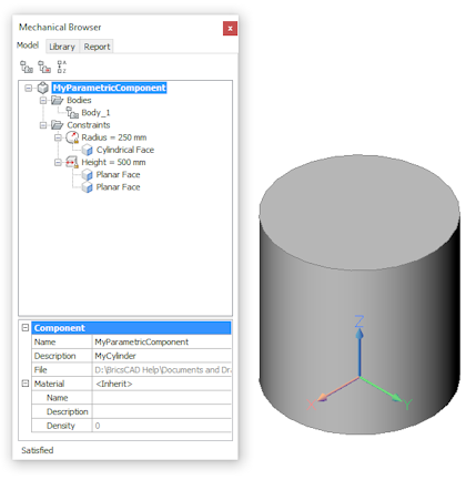
To edit the parameters of a component insert
When a parametric component is inserted in a model, you can edit the parameters either in the Mechanical Browser panel or in the Properties panel.
The component insert immediately updates according to the new value of a parameter. Please note that this does not modify the definition of the parametric component, which is a separate drawing file. As a result, multiple inserts of the same parametric component can exist in the same model, with different values for each of their parameters:
To edit a parameter in the Mechanical Browser
- Expand the Parameters node of the component.
- Select the parameter.
- In the Parameter section, type a new value in the Expression field.
To edit a parameter in the Properties bar
- Select the component in the drawing.
- Expand the Parameters settings group.
- Type a new value for one of the available parameters.
- In the Properties panel, the current value is displayed. If this value is controlled through an expression, the expression will be overwritten by the newly entered value.
- If multiple parametric components are selected, the shared parameters can be edited simultaneously. The settings fields of parameters that currently have different values reads: *varies*.
To replace components
The BMREPLACE command replaces component inserts. Only top-level inserts can be replaced.
Components, blocks or external references?
Components are based on blocks and external references (Xrefs) but the behavior of components is different. An external component is linked to a file, much like an Xref, but an external component can be represented by either an Xref (BMINSERT acts like XATTACH) or by a local anonymous block (BMINSERT acts like INSERT).
Components can be either parts or assemblies:
- Part: composed of entities only; no inserts of subcomponents.
- Assembly: composed of entities and subcomponent inserts. Even when the subcomponents are removed, the assembly status is kept.
When an external component is a part and its parameters are not modified, the component is inserted as an Xref. This is listed in the External References section of the Drawing Explorer dialog. Xref layers have a 'file_name' prefix.
When an external component is an assembly, it is inserted as a local anonymous block. All of its layers are merged with the layers of the main document and no prefix is added to the layer name.
Converting blocks and external references
The BMMECH command converts the current drawing into a mechanical component. If the drawing already is a mechanical component BMMECH does nothing.
Block references are converted to inserts of local components and external references are converted to inserts of external components.
The BMUNMECH command converts the current mechanical component into a plain drawing. Mechanical components are converted back to blocks and external references. The command applies to drawings that are a mechanical component only.
Component-based features
A feature is a physical constituent of a part with engineering significance. Examples of features are holes, ribs, slots, pockets, forms. If applied to a 3D solid, a feature removes and/or adds geometry. To create your own features, use the BricsCAD component extension technology.
An extended component has BC_SUBTRACT and/or BC_UNITE layers. When you use the BMINSERT command to insert such a component on the face of a 3D solid, the target solid is modified as follows:
- All 3D solids on the BC_SUBTRACT layer of the component are subtracted from the target 3D solid.
- All 3D solids on the BC_UNITE layer of the component are united with the target 3D solid.
All faces created after Boolean operations form a component-based feature. They are updated when you move the component insert or when you modify any parameters. When the insert is deleted, the target solid is healed. Adjust the target 3D solids with the BMLINK command.
Some examples of parametric component-based features are included with BricsCAD. You can use them as samples to create your own features.
Assign physical materials to components
You can assign a physical material to a mechanical component. If a mechanical component does not have an assigned material, it will inherit the material from its parental component. If the parental component does not have an assigned material, the material of the nearest component, will be used. As a result, the same material can be assigned to all components that have a common parent.
- Select the root component in the Mechanical Browser.
- Select the Material property and press the
Browse button (
 ).
). - In the Physical Materials dialog box, select a material
from either the In Project or the In
Library list.
Materials that are chosen from the In Library are copied to the In Project database automatically.
- Click the OK button to assign the selected material to the component.
To remove the material from the component:
- Select the root component in the Mechanical Browser.
- Select the Material property and press the Clear button (X).
Inserting a component with a physical material:
When you insert a mechanical component in a model, all its materials are copied to the material library of the model. If a material with the same name already exists in the target model, this material will be used instead. As a result, the properties of the material in the target model are used. This replaces the properties of the material from the inserted component.
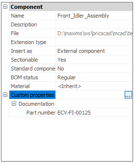
Assign custom properties to components
You can assign custom properties to components and component inserts. Similarly to BIM custom properties, component custom properties are grouped into property sets, that correspond to groups in mechanical browser or properties panel. A property set contains property definitions, which define the name and the type of this custom property. You may also add predefined values for a specific custom property.
By default, property sets are applicable for all mechanical components in the document. For example, you may define a property set with “Part number” custom property, and this property will appear for every part in the model. If a component with this property is inserted into another document, the property will also appear for all components in that document. To avoid that, you may use per-instance property sets. Those property sets will be applied only to specified components. To enable or disable a per-instance property set for selected components, use the context menu of the mechanical browser.
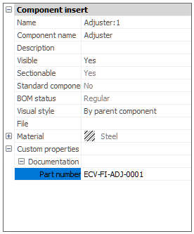
Component inserts inherit custom properties of their corresponding component. However, you are free to change any instance custom property as you wish; those changes will be applied only to selected component instances and will not affect other instances or the component itself. To change component properties, you will need to open the corresponding component and change its properties by selecting the root node in the mechanical browser.
- To change component properties:
-
- Select the root component in the Mechanical Browser.
- (optional) If necessary, configure the available custom
properties:
- Call BMPROPERTIES command from the ribbon or command line
- or select the Custom properties property and
press the Browse button ().
- (optional) If necessary, enable per-instance property sets for
this component:
- Right-click on the root node in the browser, then select necessary property sets in Custom properties submenu.
- Select a required property and type or select a new value.
- To change top-level instance properties:
-
- Select the component instance in the Mechanical Browser.
- (optional) If necessary, configure the available custom
properties:
- Call BMPROPERTIES command from the ribbon or command line
- or select the Custom properties property and
press the Browse button ().
- (optional) If necessary, enable per-instance property sets for
this component:
- Right-click on the corresponding node in the browser, then select necessary property sets in Custom properties submenu.
- Select a required property and type or select a new value.
- Select the component instance in the Mechanical Browser.