In BricsCAD®, TIN (Triangulated Irregular Network) Surface is created using the the TIN command.
A TIN surface uses two types of entry data: points and breaklines (polylines).
Points contain X, Y coordinates and Z values. All points are used to make a connection with the two nearest neighbors to create triangles. The surface triangulation is based on the Delaunay algorithm, which ensures that no point is inside the circumcircle of any triangle.
Breaklines represent linear infrastructure features like curbs, retaining walls, etc. These lines also define the edges of triangles. Breaklines can be created from linear entities such as line, polyline, arc or circle.
Boundaries are the features to define bounded 3D surfaces. The surface boundaries can be created with closed polylines. Defining outer boundaries on a large 3D surface improves the performance of a TIN Surface plan.
Creating a TIN Surface is a process that needs to be followed to map a particular area in detail. On BIM models, these surfaces are used to represent the site. The TIN surface can be generated from large data sets such us Point Clouds, from drawing entities, from 3D Faces, from custom ASCII point files, from Civil 3D surfaces.
Setting the TIN Surface preferences
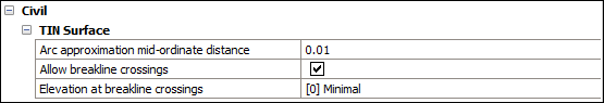
Arc approximation mid-ordinate distance
Note: Mid-ordinate distance is the maximal distance between arc and chord (straight) segment which is used for arc approximation.
Defines how many points along the curve you want to add. When you have polylines with curves, this parameter allows you to tessellate the arcs in the polyline. The default value of this parameter is variable in BricsCAD predefined templates. For instance, the distance value is set to 0.01 in BIM-m, 1 in BIM-cm, 10 inBIM-mm, and 0.4 in BIM imperial templates.
Allow breakline crossings
Defines if crossings breaklines are allowed. By default, it is set to On. If breakline crossings are allowed, intersections between breakline segments are calculated and added as points to the TIN Surface.
Elevation at breakline crossings
Defines how elevation at crossing breaklines should be determined. There are three options (e.g., minimal, maximal, and average) for defining breaklines elevation at the intersection.
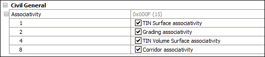
Associativity
Enable/disable grading, surface and corridor associativities.
By default, the system variable is set to 15.
0: Neither TIN surface, grading nor corridor associativity is enabled.
1: Enables TIN surface associativity.
2: Enables grading associativity.
3: Both TIN surface and grading associativities are enabled.
4: Enables TIN volume surface associativity.
5: Both TIN surface and TIN volume surface associativities are enabled.
6: Both grading and TIN volume surface associativities are enabled.
7: TIN Surface, Grading and TIN volume surface associativities are enabled.
8: Enables corridor associativity.
9: Both TIN surface and corridor associativities are enabled.
10: Both grading and corridor associativities are enabled.
11: TIN surface, grading and corridor associativities are enabled.
12: Both TIN volume surface and corridor associativities are enabled.
13: TIN surface, TIN volume surface and corridor associativities are enabled.
14: Grading, TIN volume surface and corridor associativities are enabled.
15: All TIN surface, grading, TIN volume surface and corridor associativities are enabled.
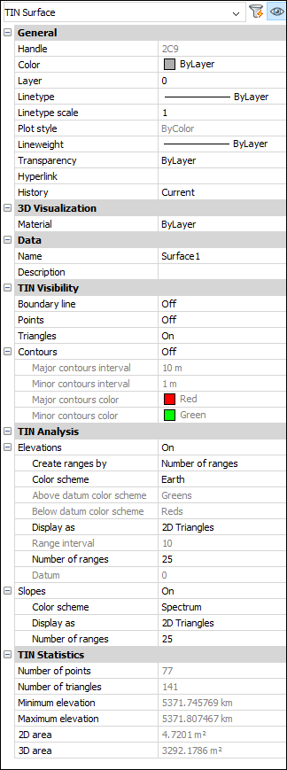
Properties of a TIN Surface
TIN Visibility
Defines the visibility of the TIN surface elements.
Boundary line
Change visibility of the outer boundary on a TIN Surface.
Points
Change visibility of points on a TIN Surface.
Triangles
Change visibility of triangles on a TIN Surface.
Contours
Defines the visibility of contours on a TIN Surface.
Major contours interval
Sets the major contours interval.
Minor contours interval
Sets the minor contours interval.
Major contours color
Defines the color of the major contour.
Minor contours color
Defines the color of the minor contour.
TIN Analysis
Defines the parameters for displaying elevations and slopes analyses.
Elevations
If ON, this option defines the parameters for displaying elevations analyses.
Create ranges by
Sets the range type (Number of ranges, Range interval, Range interval with datum).
Color scheme
Sets a color scheme for the elevation analysis.
Above datum color scheme
Sets the above datum color scheme.
Below datum color scheme
Sets the below datum color scheme.
Display as
Sets the type of entities that will be used for displaying elevation analysis (Triangles, Contours, Points, 2D Triangles, 2D Contours)
Range interval
Sets the range interval.
Number of ranges
Sets the number of ranges.
Datum
Sets the datum.
Slopes
If ON, this option defines the parameters for displaying slopes analyses.
Color scheme
Sets the color scheme for slopes.
Display as
Sets the type of entities that will be used for displaying slopes analysis
(Triangles, 2D Triangles).
Number of ranges
Sets the number of ranges.
TIN Statistics
Displays the TIN Statistics.
The number of points
Displays the number of TIN Surface points.
The number of triangles
Displays the number of TIN Surface triangles.
Minimum elevation
Displays the minimum elevation value found in the TIN surface.
Maximum elevation
Displays the maximum elevation value found in the TIN surface.
2D area
Displays the 2D area of the TIN surface.
3D area
Displays the 3D area of the TIN surface.
Procedure: Creating a TIN Surface from drawing entities
Open the drawing that contains drawing entities, such as CAD points, blocks and polylines.
Launch the TIN command.
Select all entities in the drawing.
Press ENTER
Select an option in command line to apply selected linear entities as Breaklines.
Note: TIN Surface maintains a live connection to linear drawing entities when they are added as Breaklines. When editing such drawing entities, the TIN surface is automatically rebuilt. If linear drawing entities are added to a TIN Surface as edges or points, this connection is not maintained. The same applies to CAD blocks and points.
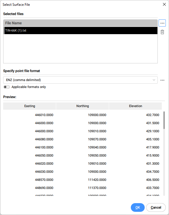
Procedure: Creating a TIN Surface from a point file
Launch the TIN command.
Select Import from file in the Command line.
In the Select Surface file dialog box, select the point data file that you want to open, or choose multiple files to import all at once.
Specify point file format from the drop-down list.
Note: click the browse button in the Specify point file format section to manage surface file formats.
Toggle the Applicable formats only to automatically filter appropriate point file formats, according to the selected input point file(s).
Click OK to create TIN Surface from a point file.
Select "No" in a command line to create TIN Surface without simplifying points.
Note: Check the description of the TIN Simplify algorithm for detailed explanation of the parameters.
Procedure: Creating a TIN Surface from a point file using Clip polygon
Use existing or create a new closed polyline to create a TIN Surface inside that area.
Launch the TIN command.
Select the cLip polygon option in the Command line.
Select a closed polyline in a drawing to be used as a clipping polygon.
Select an option Import from file in a command line to create TIN surface from a point file inside the selected clipping polygon.
Note:Note: Select any other option: select (drawing) entities, create from Faces, create from Point Cloud, create from Point Groups.
Follow the procedure for creating a TIN Surface from a point file, which is described in this article.
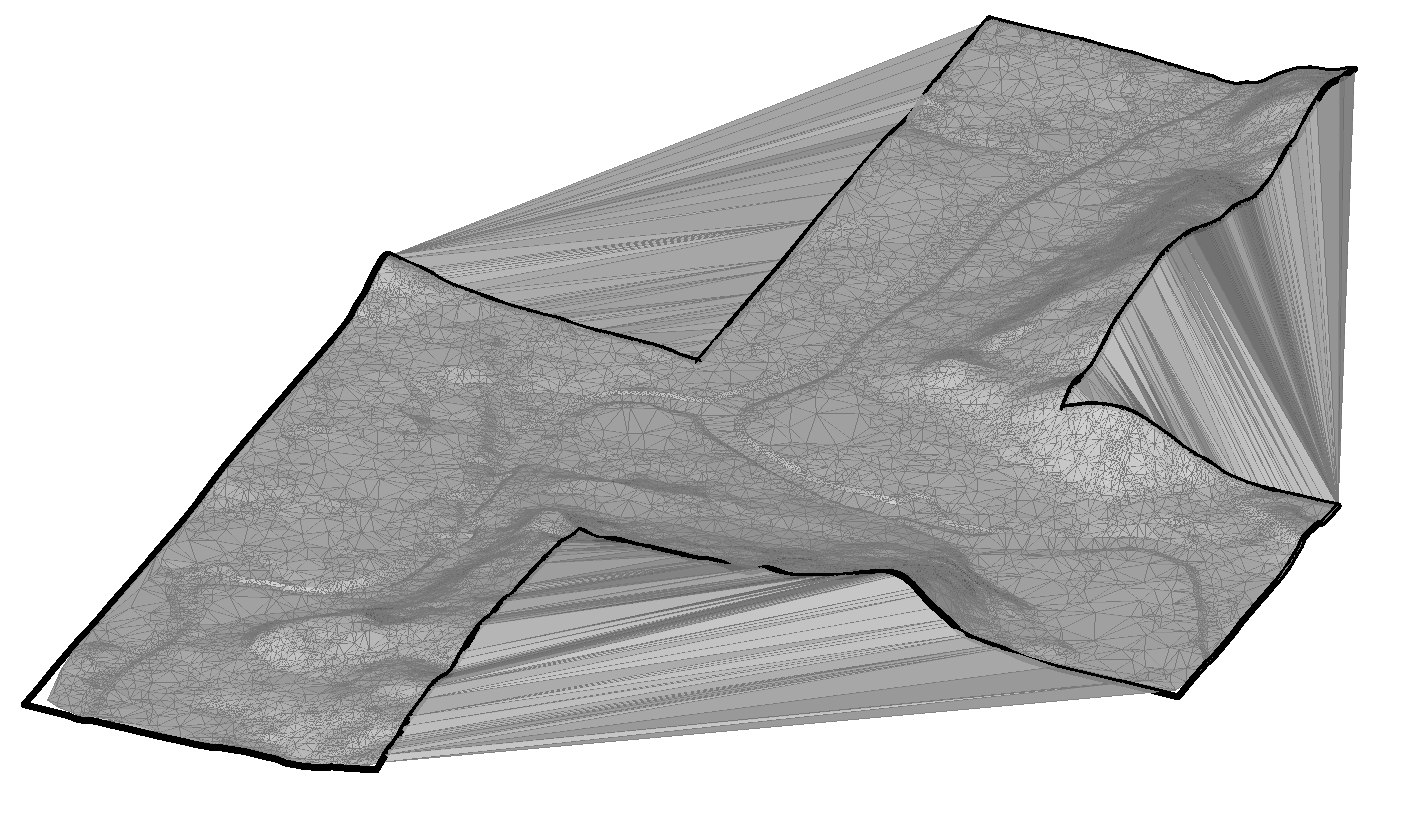
Note: The TIN surface algorithm connects triangles outside the boundary of the concave clipping polygon. In such areas, long and narrow triangles are created, which can be removed with the TINEDIT command.
Launch the TINEDIT command and select an option "Remove Outer Edges". Then specify the maximum triangle length. Triangles that are longer than specified value are removed.
Procedure: Creating a TIN Surface by placing points
Open a drawing.
Launch the TIN command.
Select the place Points option in the Command line.
Pick a point where you want to start creating a TIN surface.
Specify the elevation value of each of those points, then press ENTER to accept.
Note: At least three points are needed to create a TIN surface.
Procedure: Creating a TIN Surface from Faces
Open a drawing file that contains 3D faces.
Launch the TIN command.
Select the create from Faces option in the Command line.
Select desired 3D faces.
Select an option whether to apply 3D Faces as edges (and visibility) or not.
Note: If this option is selected, then edges and vertices of the 3D Faces are used to create the TIN surface. Otherwise, only the vertices of the 3D faces are used to create the TIN surface. As a result, the TIN Surface does not follow the edges of the 3D Faces.
Procedure: Creating a TIN Surface from a Point Cloud
Open the drawing file that contains a point cloud.
Launch the TIN command.
Select an option "Create from point cloud" in a command line.
Select a point cloud in the drawing.
Press ENTER.
Select "No" to create TIN Surface without using the simplification method.
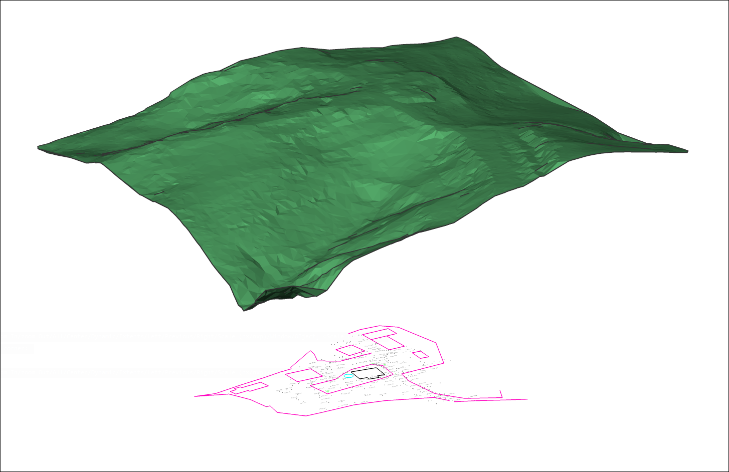
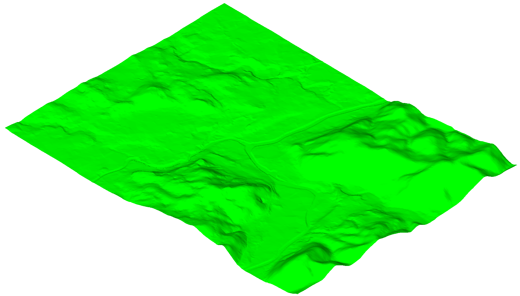
Image shows original TIN Surface created from a Point Cloud with 87350 points.
Procedure: Use TIN Simplify and TIN Densify options when creating TIN Surface from a Point Cloud
This section describes the procedure of creating a TIN Surface from a Point Cloud, where we also use the TIN Simplify and TIN Densify options.
Follow steps 1 to 5 from the procedure described above to create a TIN surface from a Point Cloud. Then, follow the procedure below to use TIN Simplify and TIN Densify options.
Select "Yes" when command line offers the option to simplify TIN surface.
Enter radius for simplification step.
Enter Elevation difference.
Note: Check the description of the TIN Simplify algorithm for detailed explanation of the parameters.
Select "Create TIN Surface" in a command line.
Or select an option "Simplify again" to edit the simplification parameters.
Note: The command line reports the number of points before and after simplification so that the user can make a better decision for the next steps.
Select "Yes" to Densify TIN Surface.
Or select "No" to create simplified TIN Surface.Image Shows simplified TIN Surface with 1562 points.
Enter elevation difference.
Select one of the options to specify the area for TIN Densify process: select existing polygons in a drawing, draw a new polygon or press ENTER to use entire TIN Surface.
Note: Check the description of the TIN Densify algorithm for detailed explanation of the parameters.
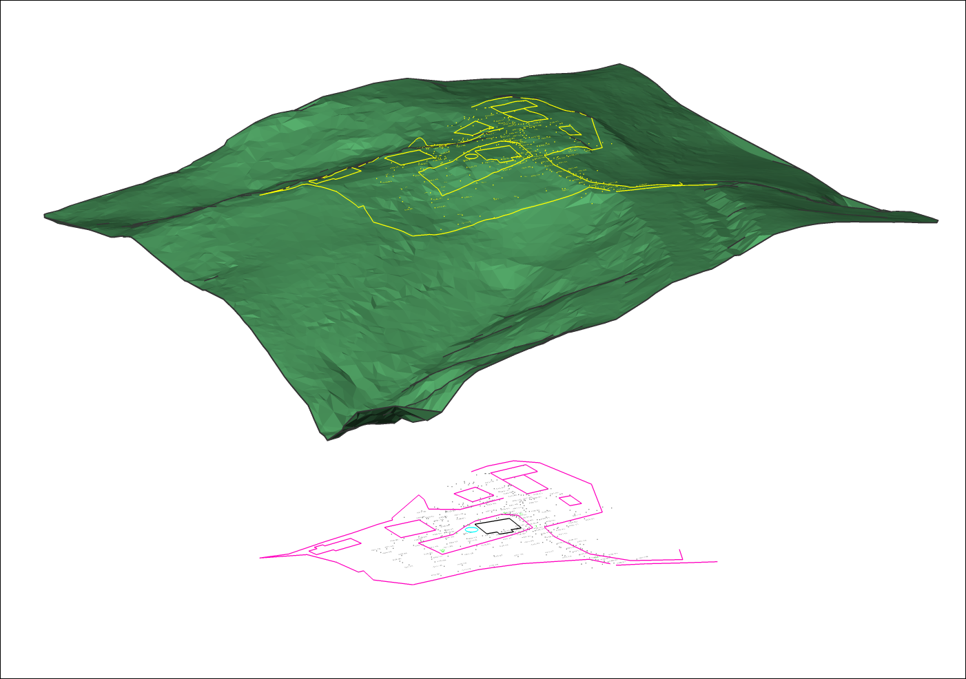
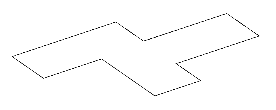
Image shows a polygon that defines an area for TIN densification.
Note: The final result represents a simplified TIN surface to which individual points within the specified polygon are returned. By using TIN Densify option on a specific area on the entire TIN Surface, we achieve the goal that in this area the elevation difference between the original and the final TIN surface is never greater than the specified value of the "elevation difference" in step 6.
Image shows a final TIN Surface with 6536 points. Original TIN Surface consists of 87350 points.
Note: You can edit the TIN Simplify and TIN Densify parameters at any time in Civil Explorer. Select the appropriate TIN Surface, right-click on the "Add points" definition and select "Edit" option from the context menu. The Surface definition dialog box opens in which you can edit all the necessary parameters.
Procedure: Creating a TIN Surface from a Civil 3D surface
Open a drawing with a Civil 3D surface.
Launch the CIVIL3DIMPORT command.
In the Import Civil 3D dialogue box, select Convert from current drawing.
Note: Select AutoCAD Civil 3D Surfaces that will be converted to BricsCAD Civil TIN Surfaces.
Note: In the "Import Civil 3D" dialog box, you can also select other Civil 3D objects, such as Point Groups, Alignments and Profiles, that will be converted to BricsCAD Civil elements.
Specify the name template for Civil 3D objects.
Tick the option Import Civil 3D labels as blocks.
Click the OK button.
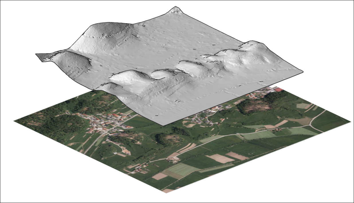
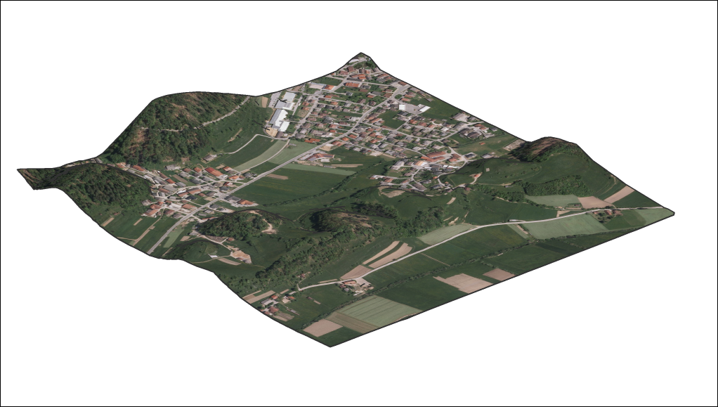
About TIN Assign Image
Open the drawing file that contains a TIN surface and an image.
Launch the TINASSIGNIMAGE command.
Select the TIN surface.
Select the raster image.
Note: If the image is not shown on the TIN surface, change the Visual Style to Modeling or Realistic and set TIN surface triangles to ON.
About TIN Project
Open the drawing file that contains the TIN surface and the entities (points, blocks, text, lines, polylines, circles…).


 Note: The TIN surface algorithm connects triangles outside the boundary of the concave clipping polygon. In such areas, long and narrow triangles are created, which can be removed with the TINEDIT command.
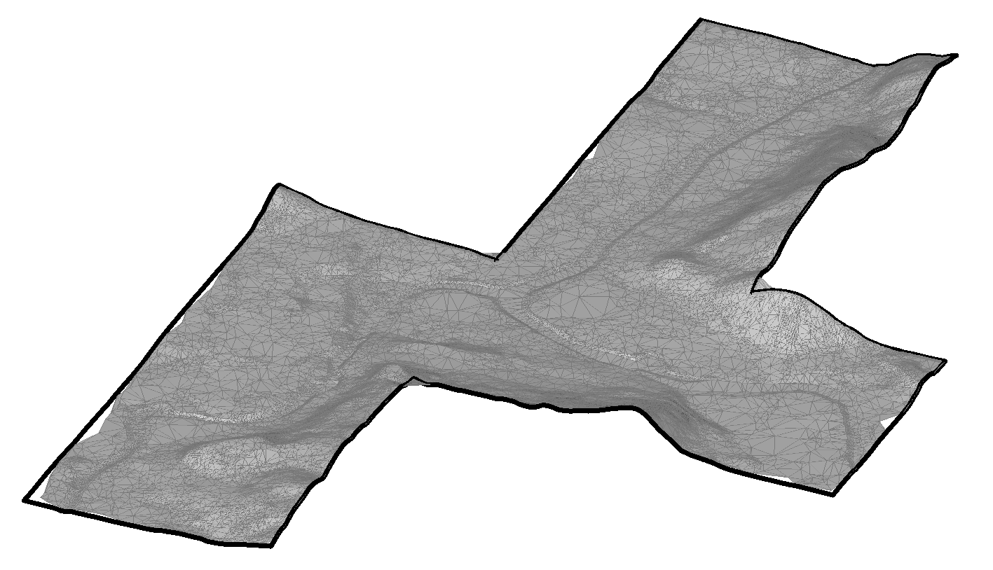
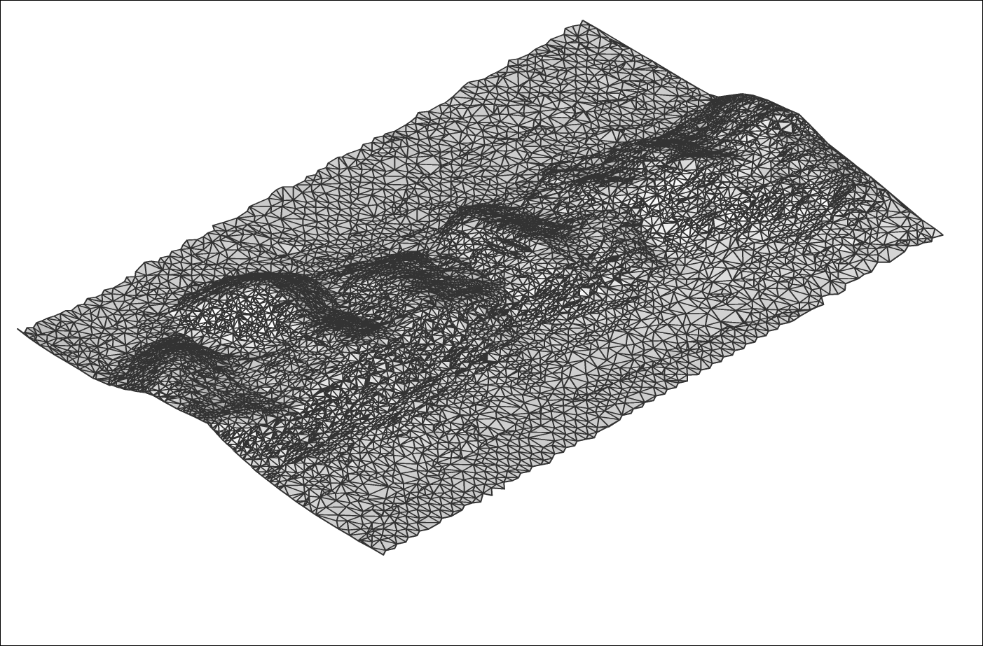
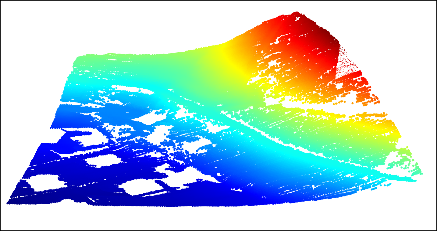
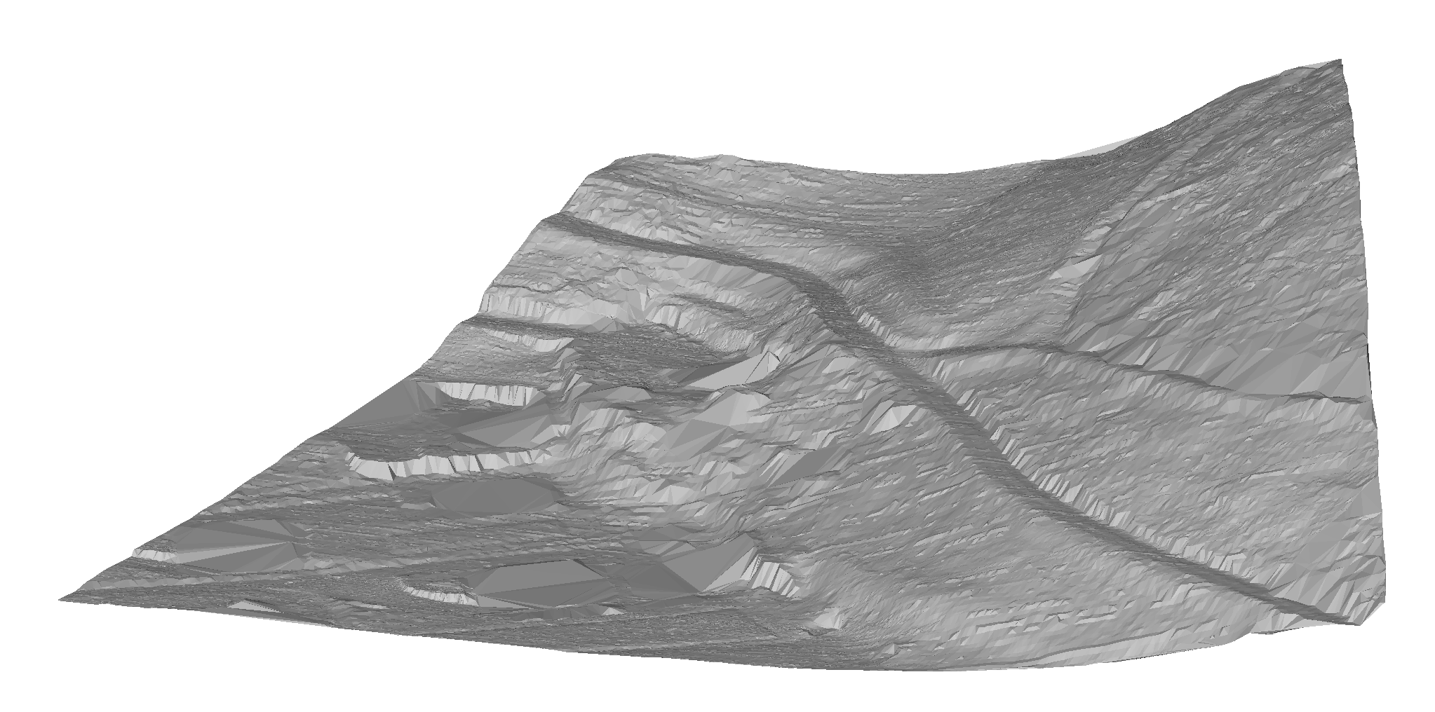
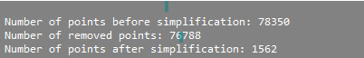
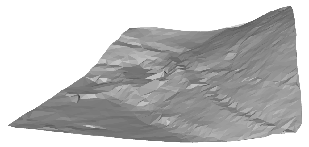
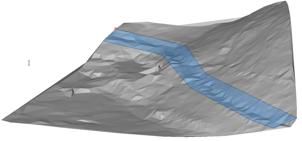 Image shows a polygon that defines an area for TIN densification.Note: The final result represents a simplified TIN surface to which individual points within the specified polygon are returned. By using TIN Densify option on a specific area on the entire TIN Surface, we achieve the goal that in this area the elevation difference between the original and the final TIN surface is never greater than the specified value of the "elevation difference" in step 6.
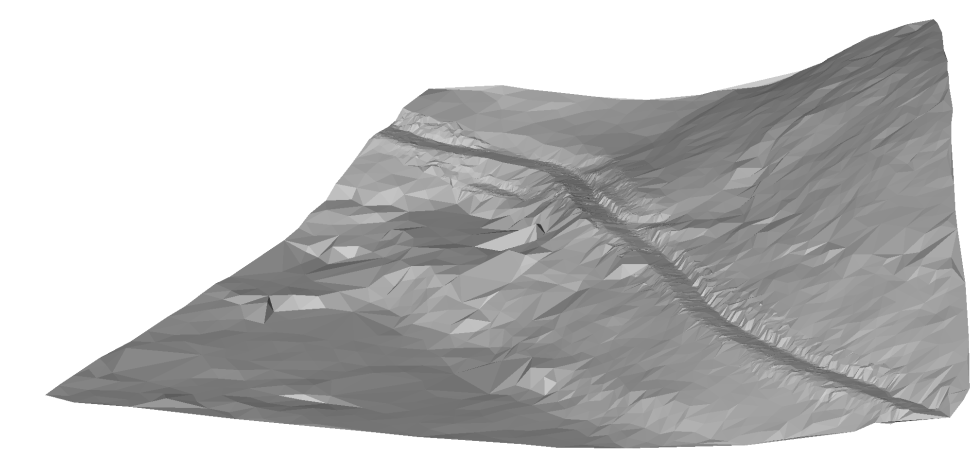 Image shows a final TIN Surface with 6536 points. Original TIN Surface consists of 87350 points.Note: You can edit the TIN Simplify and TIN Densify parameters at any time in Civil Explorer. Select the appropriate TIN Surface, right-click on the "Add points" definition and select "Edit" option from the context menu. The Surface definition dialog box opens in which you can edit all the necessary parameters.
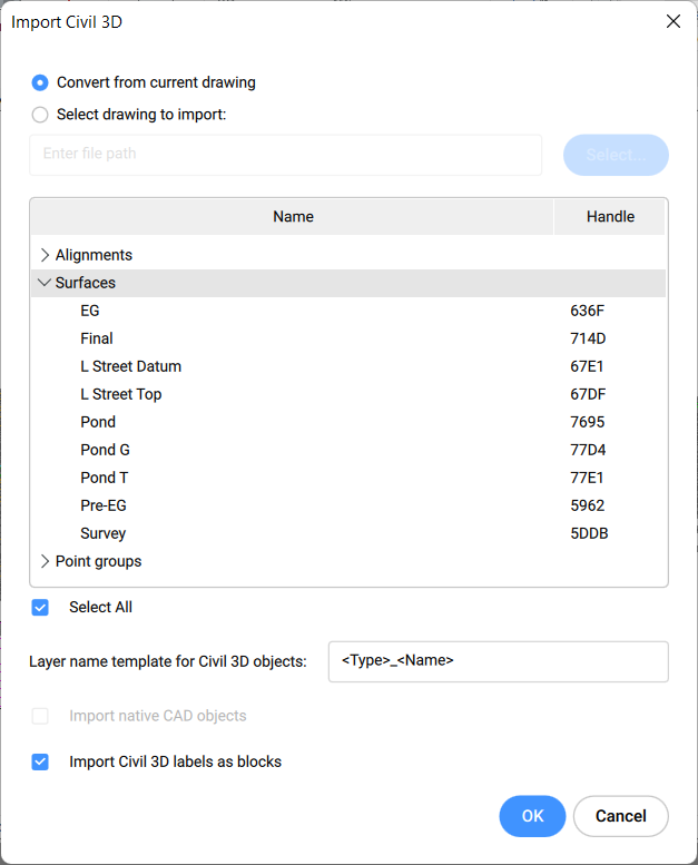
 Note: If the image is not shown on the TIN surface, change the Visual Style to Modeling or Realistic and set TIN surface triangles to ON.