Several alignment editing options are available in BricsCAD Civil, using the
ALIGNMENTEDIT command:
Continue a horizontal or vertical alignment;
Add or delete Pi/Pvi points;
Delete elements;
Add or remove Station equations;
Change the TIN Surface
Note: The 3D alignment is updated automatically.
Continuing a horizontal alignment with ALIGNMENTEDIT
Draw a horizontal alignment following the steps from the Create
alignments article, Creating an alignment by PI.
Type ALIGNMENTEDIT in the Command line.
Select the horizontal alignment you want to edit.
Select the option Continue by Pi in the Command
line.
Pick new horizontal alignment PI points to continue your existing
alignment.
Use the Undo option in the Command line to return to the
previous step.
Press enter when finished. In doing so, the horizontal alignment is extended
accordingly, and the 3D alignment is updated automatically.
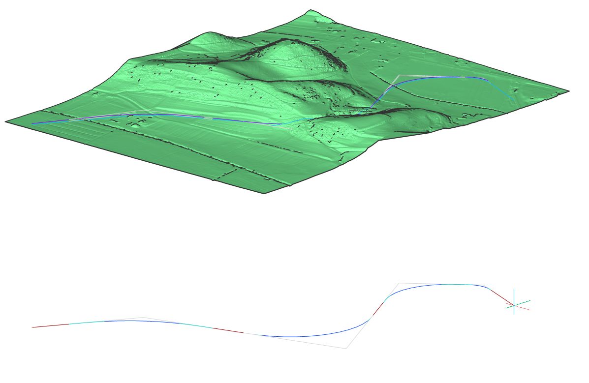
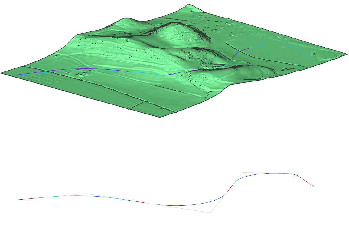
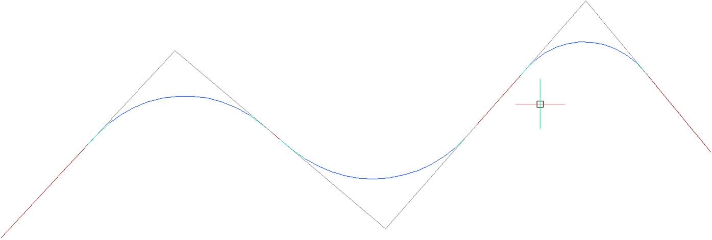
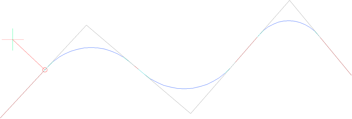
Adding PI to an existing horizontal alignment
Type ALIGNMENTEDIT in the Command line.
Select the horizontal alignment you want to edit.
Select the option Add Pi in the Command line.
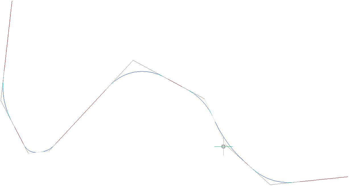
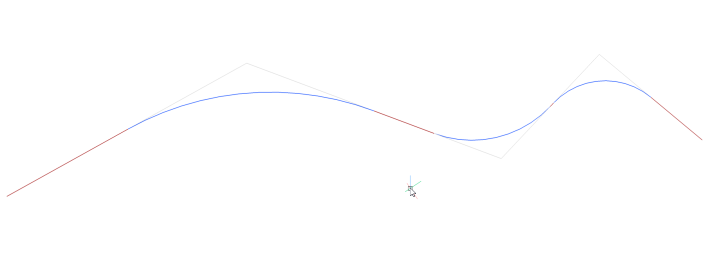
Pick point to add new PI.Figure 1. Before adding PI pointFigure 2. After adding PI point
Removing PI from existing horizontal alignment
Type ALIGNMENTEDIT in the Command line.
Select the horizontal alignment you want to edit.
Select the Remove Pi option in the Command line.
Pick a point near PI to remove.
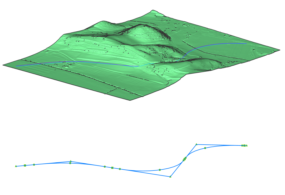
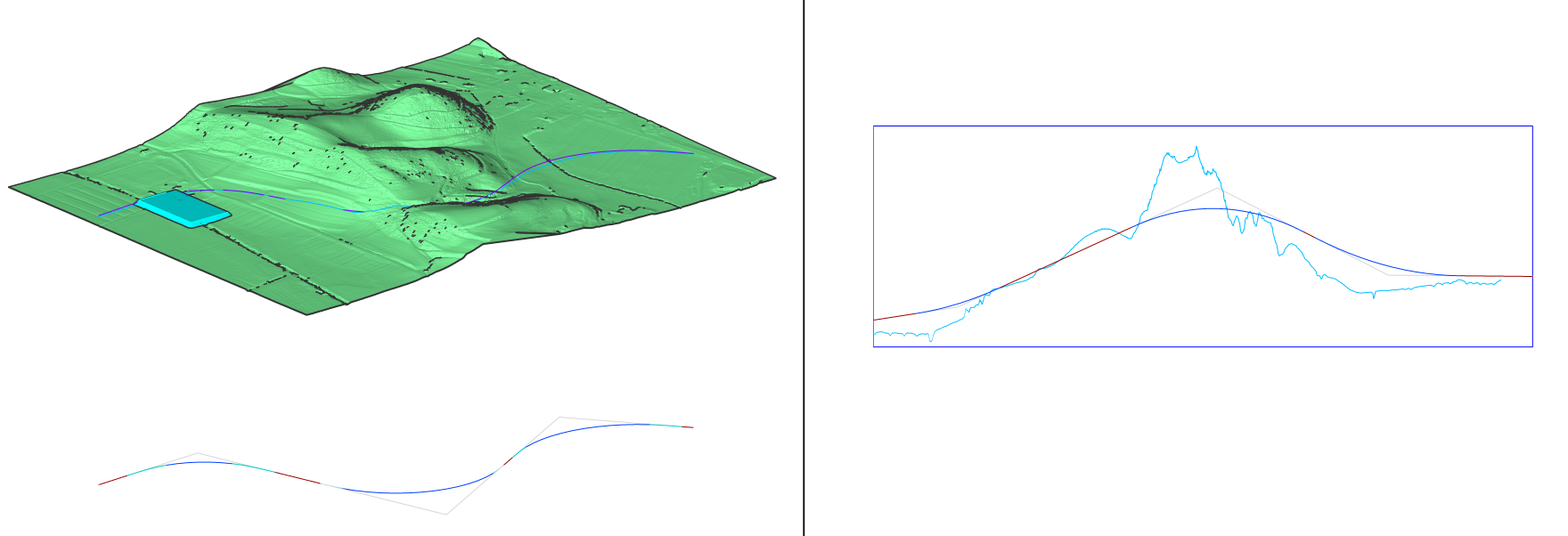
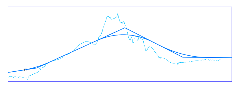
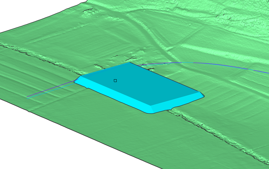
Adding additional TIN Surface to Vertical alignment view
Open the drawing file that contains a TIN Surface, Alignments, Vertical
Alignment View and grading.
Launch the ALIGNMENTEDIT command in the Command line.
Select the change Tin surface option in the Command
line.
Select the TIN surface to add.
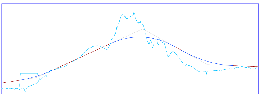
In the vertical alignment view, you can see an additional light blue line
representing the grading object.
Edit Alignments through the Properties panel
You can edit the alignment parameters through the Properties
panel.
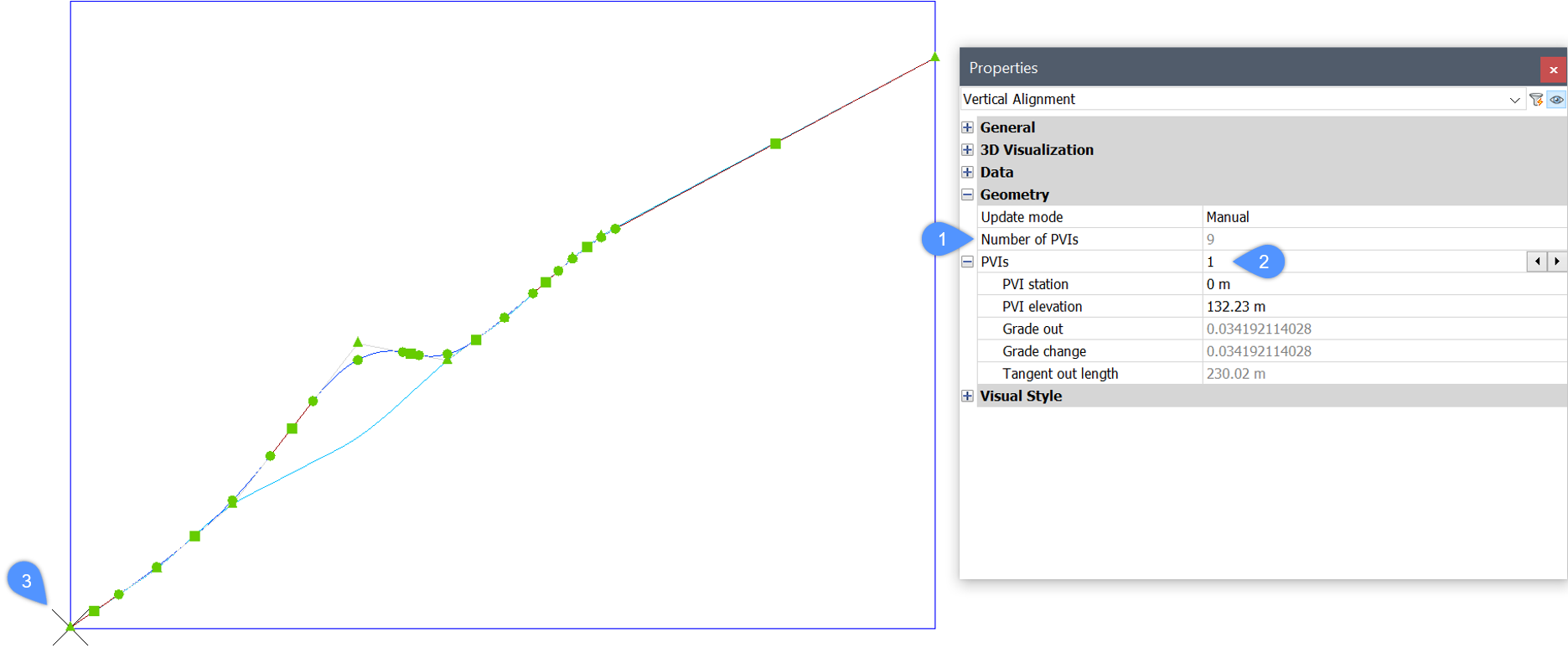
Edit Vertical Alignment
Select a Vertical Alignment.
In the Properties panel, you can see that
the Vertical Alignment consists of a number of PVIs
(1).
Once click on the PVI field (2), the
currently selected PVI is highlighted in the drawing (3).
You can switch between PVIs and edit the Alignment PVI
parameters. The Vertical Alignment will be automatically
updated in the drawing.
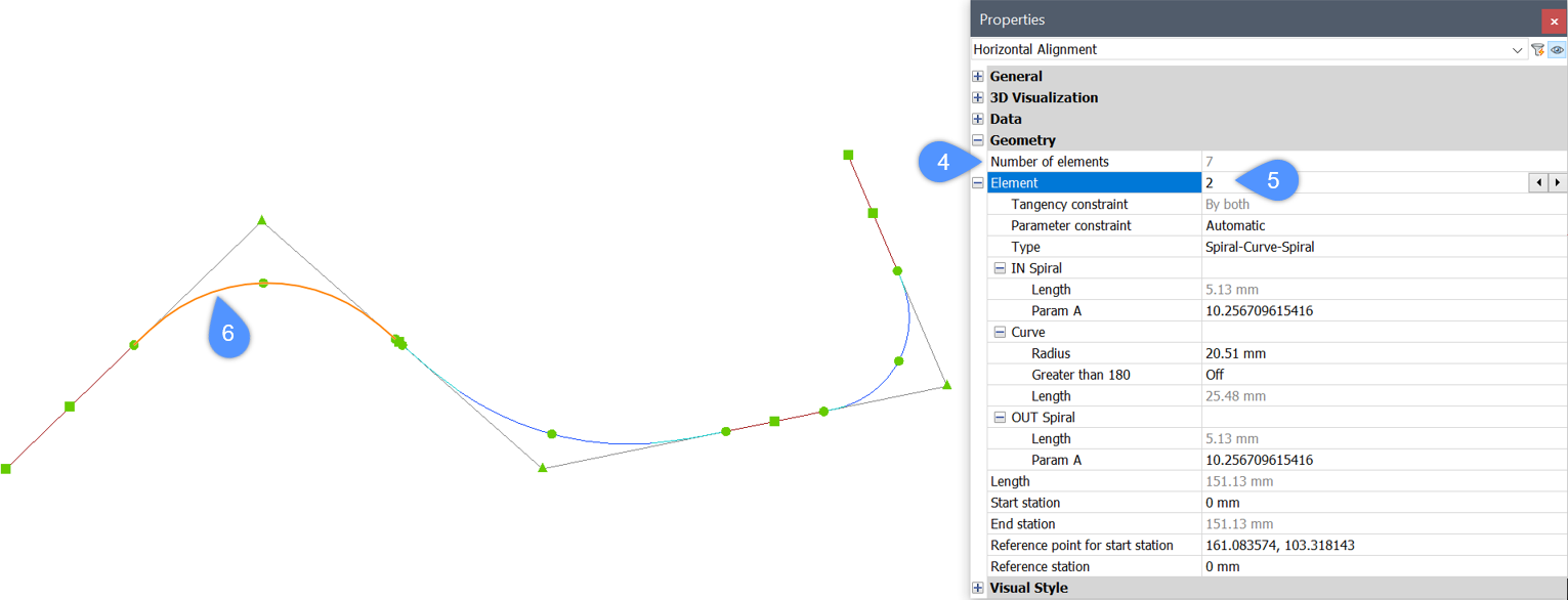
Edit Horizontal Alignment
Select a Horizontal Alignment.
In the Properties panel, you can see that
the Horizontal Alignment consists of a number of elements
(4).
Once click on the Element field (5), the
currently selected element is highlighted in the drawing
(6).
You can switch between elements and edit the Alignment element
parameters. The Horizontal Alignment will be
automatically updated in the drawing.
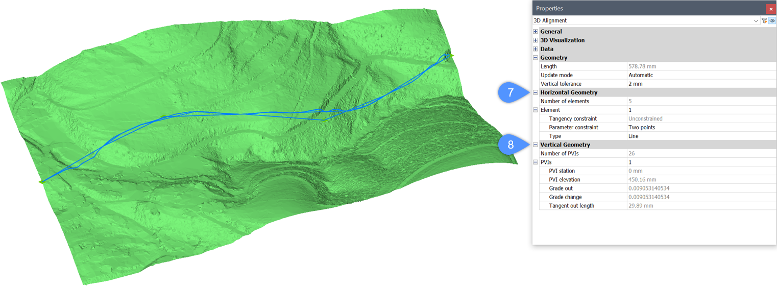
Edit 3D Alignment
Select a 3D Alignment.
In the Properties panel, you can edit its
Horizontal (7) and Vertical (8) alignment parameters.
As described above, you can switch between elements and PVIs and
change their parameters. The 3D Alignment will be
automatically updated in the drawing.
Working with alignment station equations
The alignment station equation can be set and changed as desired.
Adding station equation to an existing Horizontal alignment
Type ALIGNMENTEDIT in the Command line.
Select the Horizontal alignment you want to edit.
Select the Add Station equation option in
the Command line.
Pick point to add new Station
equation
Removing station equation from an existing horizontal alignment
Type ALIGNMENTEDIT in the Command line.
Select the Horizontal alignment you want to edit.
Specify the index number of station equation you want to
remove.
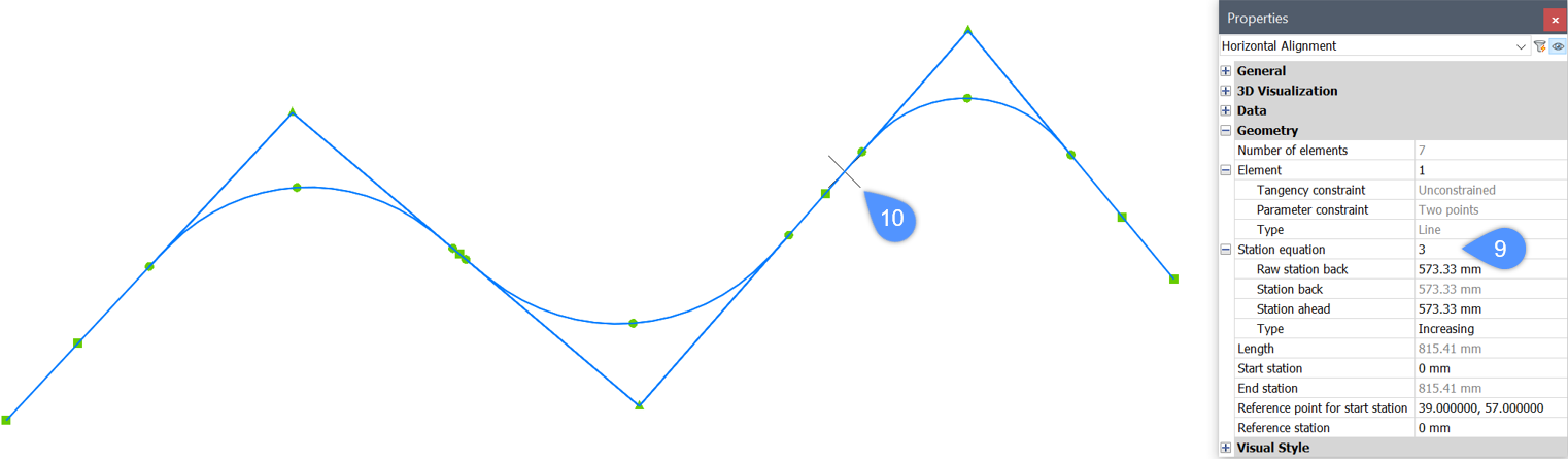
Editing station equation parameters through the Properties panel
You can switch between created Station equations
and edit the parameters in the Properties
panel.
Select a Horizontal Alignment.
In the Properties panel, you can see if
the Horizontal Alignment have station equations
added.
Once click on the Station equation field (9), the
currently selected station equation is highlighted in the
drawing (10).
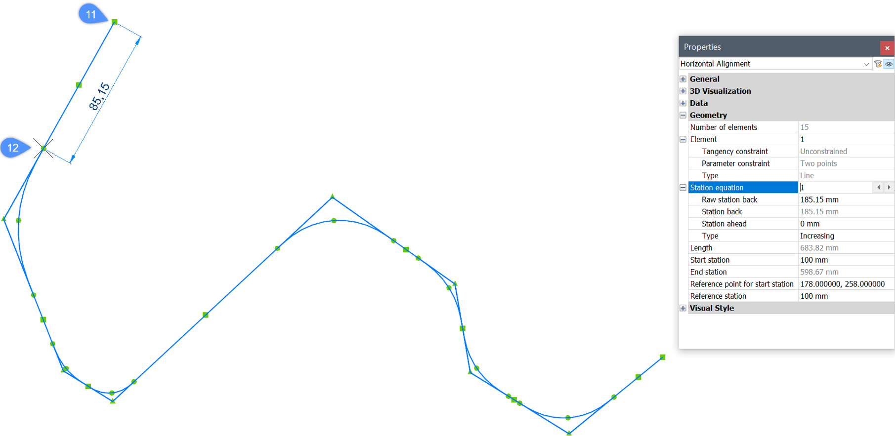
The Raw station back value is
relative to the Alignment start point (11) and the
specified point for the Station
Equation (12).
Note:Start
station at the Alignment start point
may be different from zero (specified by the user).
If only one Station Equation
is defined on the Alignment, then Raw
station back value matches to
Station back
value.
Edit the Raw station
back parameter in the Horizontal
Alignment Properties to move the point for the
Station Equation on the
Alignment.
The Station back value of all
Station equations, except for the first one, is relative
to the Station equation value and
the Station ahead value, placed
directly before it. If only one Station Equation is
defined on the Alignment, then Station
back matches to Raw station
back.
The Station Ahead specifies the
new station value starting after the new point for the
Station Equation location on
the Alignment.
The Type parameter specifies
whether the stations increase or decrease after the
(point for the) Station Equation location on the
Alignment.