Working with gradings
Overview
In BricsCAD, graded surfaces are created using the GRADING command.
Grading is a set of processes to maintain a base level for construction works or TIN surface design by defining a slope or adjusting the offset of a grading. For instance, creating parking areas, recreation reserves or road and railway designs.
Two projection methods Slope to surface and Offset to slope are supported:
- Slope to surface needs an input entity (e.g., polyline, line, arc, circle), a surface and slope to grade the surface.
- Offset to slope needs an input entity, offset and slope.
You can edit graded surfaces with the GRADINGEDIT command.
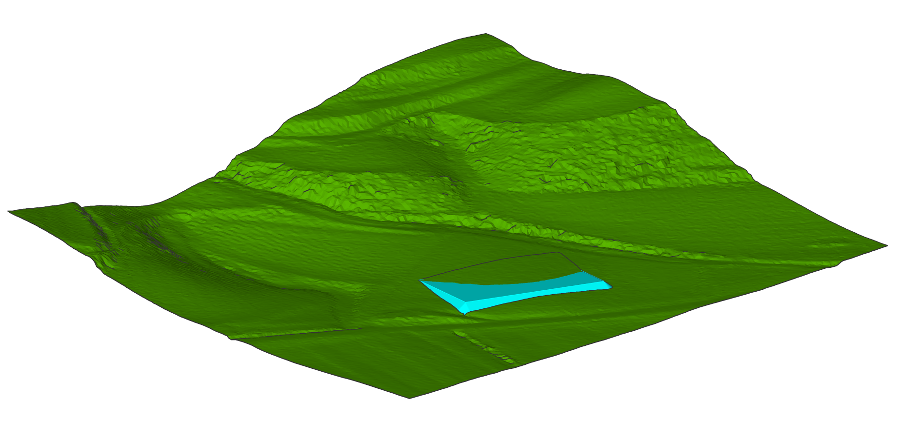
Grading a surface to create a pond
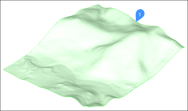
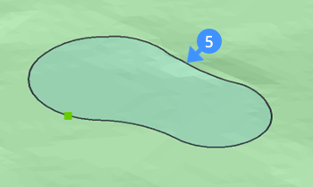
- Open a drawing that has a topographical surface (1).
- Launch the GRADING command.
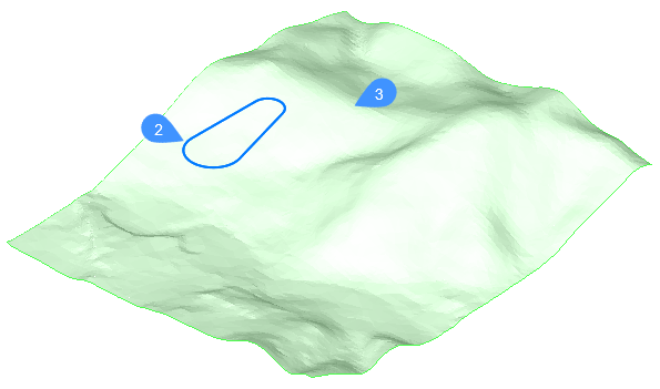
- Select the input entity (2) that defines the footprint area of your pond. Different types of opened and closed entities are accepted as input entities, such as lines, polylines, 2D/3D polylines, arcs, 3D Alignments, and gradings.Note: Before selecting the target surface, you can change to slOpe/offset projection method which requires an input entity, offset and slope.
- Select the target surface (3).
- Select a part of the entity by picking the start and end points, or the Entire length of the entity.
- Define the slope of the grading.Note: The grading is attached to the input entity, and it is connected with the target surface (TIN surface). Moving the mouse in/out dynamically increases/decreases the slope of the grading.Note: If DYNMODE variable is set to 3, you can also input the slope angle directly from keyboard (4).
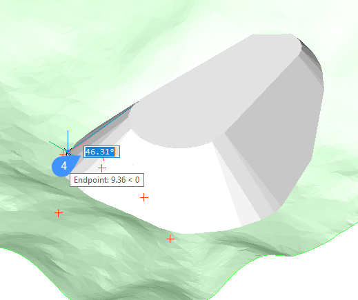
- Press ENTER to accept the slope of the grading.
Displaying the properties of a graded surface
The properties are displayed in the Properties panel after selecting the grading.
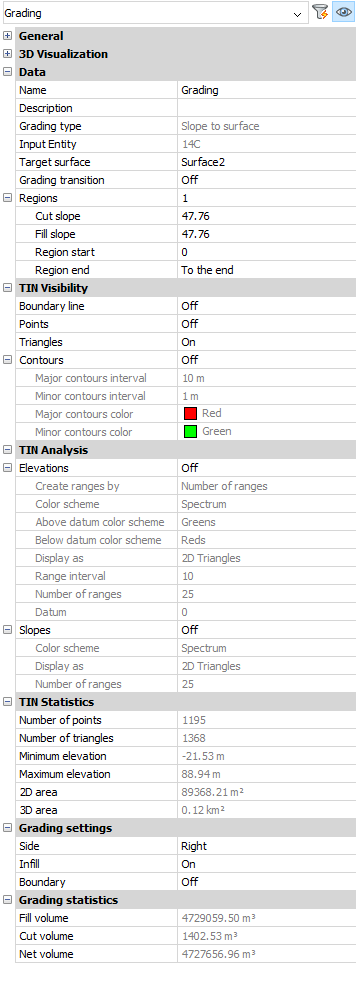
- Grading type
- Displays which projection method is used to grade the surface (Slope to surface or Slope and offset).
- Input entity
- Displays the handle number of the input entity.
- The input entity can be changed by pressing the three dots button (
 ) on the right side of the Input entity option and selecting another input entity on the screen.
- Target surface
- Displays the name of the target surface.
- The target surface of a grading can be changed by pressing the three dots button () on the right side of the Target surface option and selecting another target surface on the screen.
- Grading transition
- Displays the grading transition status.
- Cut slope
- Displays the cut slope (start and end).
- Fill Slope (start and end)
- Displays the cut slope.
- Region start
- Displays the start of the region.
- Region end
- Displays the end of the region.
As the grading is derived from the TIN surface, you have access to TIN Visibility, TIN Analysis and TIN Statistics properties. You can also calculate the TIN Volume Surface and extract the TIN surface.
- Side
- Controls on which side of the input entity the grading is drawn (left or right).
- Infill
- The internal area of entities is filled if this option is turned on. Valid for closed entities only (circle, closed polyline).
- Boundary
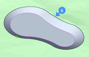
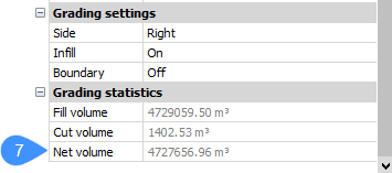
- Controls the boundary of the grading. When the grading boundary is on, that boundary is added as a hide boundary to the target surface.
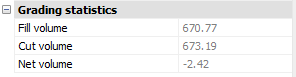
The following images show when the grading boundary of the pond is off (5) and on (6). Based on the grading boundary, the net volume for the body of the pond is calculated and can be found in the properties panel (7).
- Fill volume
- Displays the fill volume for a body/shape limited with the target surface and graded surface.
- Cut volume
- Displays the cut volume for a body/shape limited with the target surface and graded surface.
- Net volume
- Displays the net volume for a body/shape.
Grading a surface to create a platform
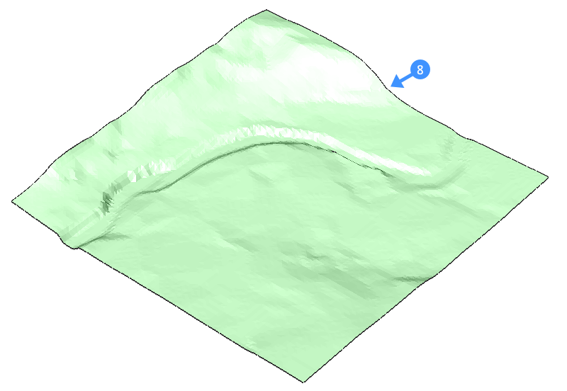
- Open a drawing that has a topographical surface (8).
- Launch the GRADING command.
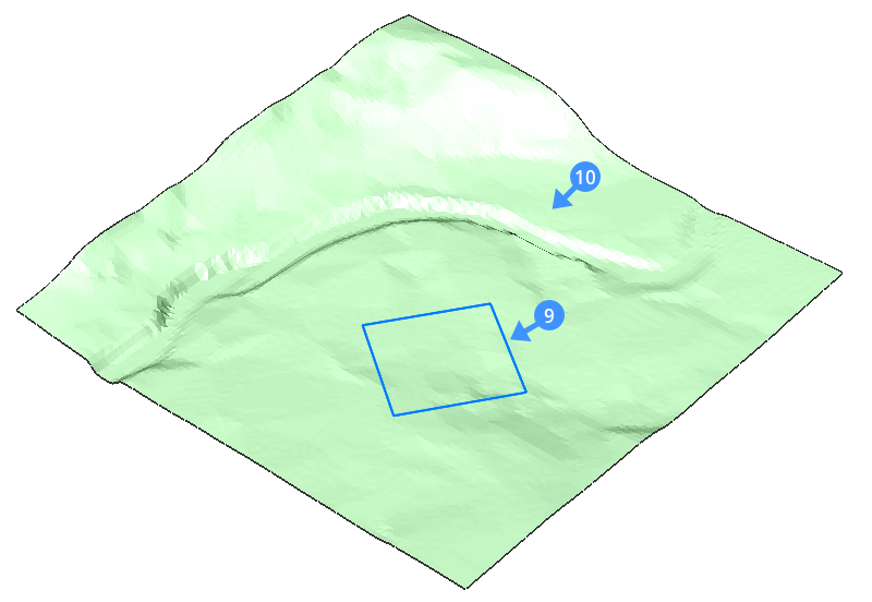
- Select the entity that defines the footprint area of your platform (9).Note: Before selecting the target surface, you can change to the slOpe/offset projection method which requires an input entity, offset and slope.
- Select the target surface (10) to create a graded area.
- Select the Entire length of the input entity.
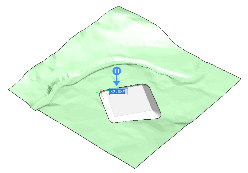
- Define the slope of the grading.Note: The grading is attached to the input entity, and it is connected with the target surface. Moving the mouse in/out dynamically increases/decreases the slope of the grading.Note: If DYNMODE variable is set to 3, you can also input the slope angle directly from keyboard (11).
- Press ENTER to accept the slope of the grading.Note: You can easily move the platform that you created. Do this by using the manipulator on the entity from which you created the platform. You can move both horizontally and vertically.
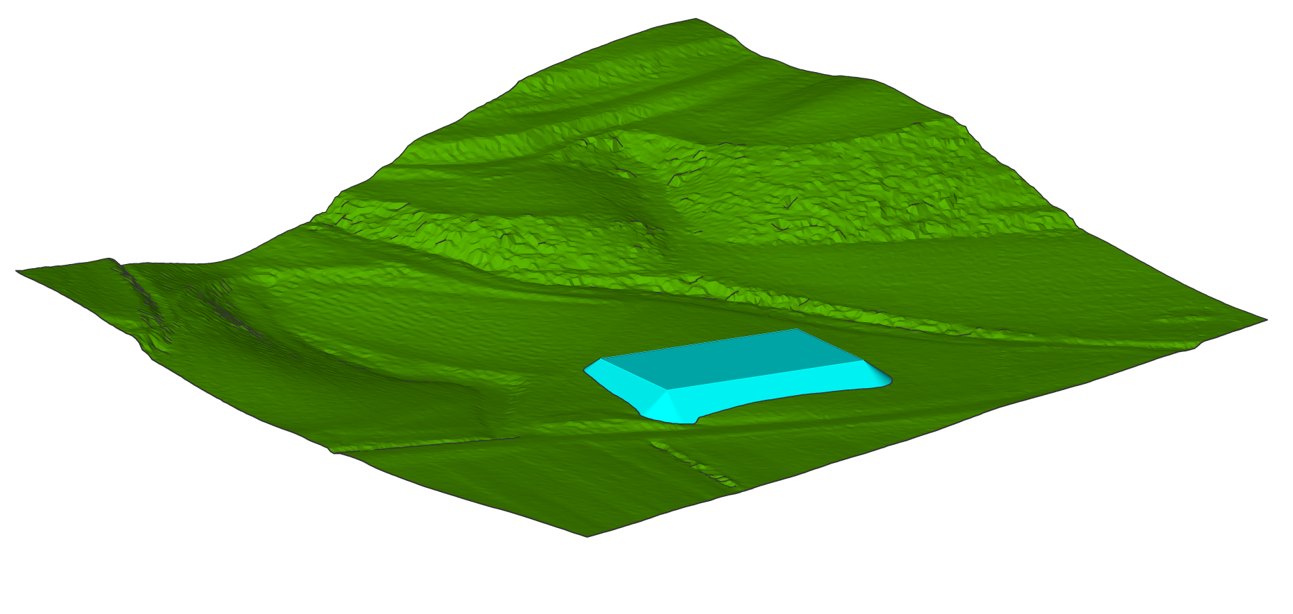
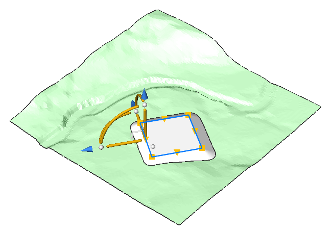 The grading will automatically be adapted to its surroundings.
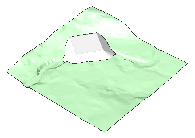
Editing a grading surface
With the GRADINGEDIT command, you can:
- Merge two gradings into one grading with several regions.
- Perform an (automatic) calculation for the transitions between gradings.
- Split a grading into multiple regions, so you can edit the slopes for each region separately.
- Merge steps:
-
- Merge Grading1 (12) and Grading 2 (13).
- Connect the grips to close the grading. The resulted grading is (14).
-
On the basis of the resulting grading (14) create another grading, that is sloped to the TIN surface, and turn OFF its Infill parameter. The resulted grading is (15).
-
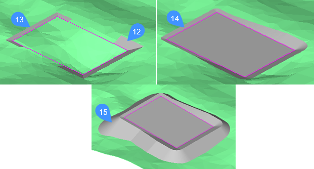
12: Grading 1
13: Grading 2
14: Merged Grading with connected grips
15: The resulted Grading with Infill parameter set to OFF
- Split
-
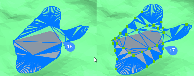
16: Grading before splitting.
17: Grading after splitting. Each region can be edited by moving the grips.
About balance grading volumes
The GRADINGBALANCE command allows you to balance cut and fill volumes within the specified tolerance. This is achieved by raising/lowering the elevation of the grading input entity and the result is grading that has a net volume around zero, depending on the set tolerance.
Adjusting the elevation of a grading to balance cut and fill volumes
- Open a drawing that contains a TIN surface and a grading representing a building pad.
- Launch the GRADINGBALANCE command.
- Select the grading.
- Enter the tolerance in percent (1-100). 1 means that the difference between the cut and fill volume will be less than one percent. 100 means that the difference between the cut and fill volume will be less than 100 percent.
In the Properties panel, you can see that the cut and fill volumes are now balanced.