


Wymiary dynamiczne
Wymiary dynamiczne zapewniają interfejs w pozycji kursora do określania długości i kąta tworzonego lub edytowanego za pomocą uchwytów elementu liniowego. W związku z tym wymiary dynamiczne pomagają skupić się na obszarze rysunku.
Zachowanie i wygląd wymiarów dynamicznych jest kontrolowany za pomocą szeregu zmiennych systemowych i preferencji użytkownika.
Definiowanie ustawień wymiarów dynamicznych
Kliknij prawym przyciskiem myszy pole DYN na pasku stanu, a następnie wybierz Ustawienia z menu kontekstowego. Ustawienia Wprowadzania dynamicznego zostaną wyświetlone w oknie dialogowym Ustawienia.
| Nazwa | Tytuł | Opis |
|---|---|---|
| DYNMODE | Tryb wprowadzania dynamicznego |
Określa, czy i kiedy są wyświetlane wymiary dynamiczne:
|
| DYNDIGRIP | Pokaż dynamiczne wymiary |
Określa, które wymiary dynamiczne są wyświetlane podczas tworzenia lub edycji elementów za pomocą uchwytów, w zależności od wartości zmiennej systemowej DYNDIVIS Długość wynikowa: całkowita długość
Długość wydłużona: przyrostowa długość linii
Kąt bezwzględny: kąt względem osi X bieżącego
Kąt względny: kąt względem pierwotnego kąta elementu liniowego
Promień łuku: promień łuków i okręgów
|
| DYNDIVIS | Widzialność wymiaru dynamicznego | Definiuje liczbę wymiarów dynamicznych, które są wyświetlane podczas tworzenia lub edycji elementów za pomocą uchwytów. |
| DYNPICOORDS | Domyślny tryb wprowadzania współrzędnych dynamicznych | Określa domyślny tryb, w którym współrzędne są wprowadzane podczas wprowadzania dynamicznego: Względny lub Bezwzględny. |
- Wygląd wymiarów dynamicznych (kolor, rodzaj linii, położenie i przezroczystość) jest kontrolowany przez zestaw preferencji użytkownika: DynDimColorHover, DynDimColorHot, DynDimDistance, DynDimLinetype, DynInputTransparency.
- Jeśli ustawiony jest kod bitowy 16 (= formatuj wymiary dynamiczne) zmiennej systemowej PROPUNITS, wymiary dynamiczne są formatowane przy użyciu dedykowanej jednostki.
- Automatyczna konwersja jednostek podczas wprowadzania długości może być użyta, gdy ustawiony jest kod bitowy 1 PROPUNITS (Właściwości długości formatu). Na przykład, gdy zmienna INSUNITS jest ustawiona na mm, wprowadzenie 2 m w polu właściwości długości spowoduje wprowadzenie [2000,0000 mm]. Wprowadzenie 1 stopę daje [304,8000 mm]. Jeśli w polu wprowadzania nie określono żadnej jednostki, używana jest jednostka określona przez funkcję INSUNITS.
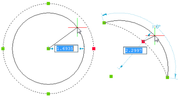
Używanie wymiarów dynamicznych podczas tworzenia elementów
- Uruchom polecenie, aby utworzyć element 2D (np. LINIA i DYNDIVIS = 1 lub 2).
-
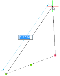
Określ pierwszy punkt, a następnie przesuń kursor, aby wyświetlić wymiary dynamiczne.
Podświetlony zostanie wymiar dynamiczny Długość .
- Wykonaj jedną z następujących czynności:
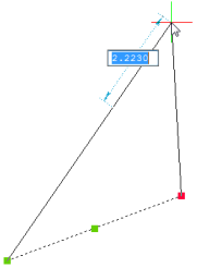
- Wpisz żądaną długość linii, a następnie naciśnij TAB, aby przejść do wymiaru dynamicznego Kąt .
Wymiar dynamiczny Długość jest zablokowany i wyświetlany na czerwono, a Kąt wymiar dynamiczny jest zaznaczony.
- Wpisz żądaną długość linii, a następnie kliknij, aby utworzyć linię pod kątem określonym przez pozycję kursora.
- Naciśnij TAB, aby przejść do Kąta wymiar dynamiczny.
- Wpisz żądaną długość linii, a następnie naciśnij TAB, aby przejść do wymiaru dynamicznego Kąt .
- Wykonaj jedną z następujących czynności:
- Wpisz żądany kąt, a następnie naciśnij Enter, aby utworzyć linię.
- Wpisz żądany kąt, a następnie naciśnij TAB, aby powrócić do Długość wymiar dynamiczny.
- Naciśnij Enter, aby utworzyć linię pod kątem określonym przez pozycję kursora.
- Naciśnij TAB, aby powrócić do Długość wymiar dynamiczny.
- Jeśli zmienna DYNDIVIS = 0, wyświetlany jest tylko jeden wymiar dynamiczny. Naciśnij TAB, aby wyświetlić następne pole.
- Jeśli wpiszesz wartość w polu Długość i dodasz przecinek (,), zawartość pola Długość zostanie skopiowana do wiersza polecenia, a znak @ zostanie automatycznie umieszczony na wierzchu, co pozwoli określić następny punkt przy użyciu współrzędnych względnych względem poprzedniego punktu.
Używanie wymiarów dynamicznych do edycji elementów za pomocą uchwytów
-
Wybierz encję lub encje.
Zostaną wyświetlone wszystkie uchwyty na wybranych elementach.
-
Kliknij uchwyt, który chcesz edytować, a następnie przesuń kursor.
W zależności od wartości zmiennej systemowej DYNDIVIS jeden, dwa lub wszystkie wymiary dynamiczne są wyświetlane jednocześnie.
Pierwszy wymiar dynamiczny jest wyróżniony.
- Wykonaj jedną z następujących czynności:
-
Wpisz żądaną wartość aktualnie podświetlonego wymiaru dynamicznego, a następnie naciśnij TAB, aby przejść do następnego wymiaru dynamicznego.
Wymiar dynamiczny jest zablokowany i wyświetlany na czerwono.
-
Wpisz żądaną wartość aktualnie podświetlonego wymiaru dynamicznego, a następnie naciśnij Enter, aby zatrzymać.
-
Naciśnij TAB, aby przejść do następnego wymiaru dynamicznego.
-
- Powtórz krok 3 lub naciśnij Enter, aby zatrzymać.
Używanie wymiarów dynamicznych do mierzenia elementów
Poniższa procedura dotyczy tylko stylu wizualnego 2DWireframe.
-
Wybierz encję lub encje.
Zostaną wyświetlone wszystkie uchwyty na wybranych elementach.
-
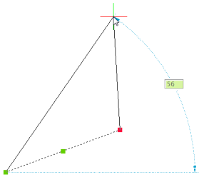
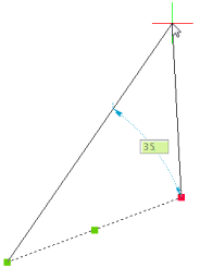
Najedź kursorem na uchwyt.
Zostaną wyświetlone podświetlenia uchwytów i wszystkie wymiary związane z wybranym uchwytem.
Wymiary dynamiczne używane do pomiaru prostokąta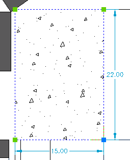 Wymiary dynamiczne używane do mierzenia linii
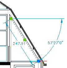
- (opcja) Kliknij, aby rozpocząć edycję wybranego uchwytu.
Używanie wymiarów dynamicznych z punktami śledzenia
Jeśli ustawiona jest opcja Śledzenie wymiarów dynamicznych zmiennej systemowej DYNMODE, wymiary dynamiczne są wyświetlane po uzyskaniu punktów śledzenia lokalizacji elementów lub tymczasowych punktów śledzenia.