


Using geometric constraints
Geometric constraints:
- Specify a geometric relation between 2 entities (coincident, concentric, collinear, parallel, perpendicular, tangent, smooth, symmetric, equal).
- Specify a fixed angle (horizontal, vertical).
- Specify a fixed location (fix).
When a geometric constrained is applied to an entity:
- The position of the entity is adjusted according to the applied constraint.
- An icon displays next to the entity, to indicate the applied constraint. If multiple geometric constraints are applied, the icons are joined in a constraint bar.
Creating geometric constraints
Tools to create dimensional constraints are located in:
- The 2D Constraints toolbar.
- The Parametric ribbon tab.
- The 2D Constraints fly-out menu of the Parametric menu.
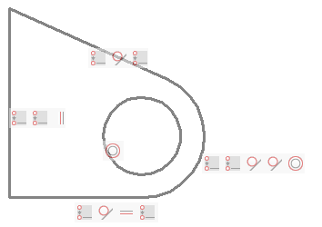
In the image below:
- The endpoints of the three lines and the arc are joined by coincident constraints.
- The midpoint of the circle and the arc are made concentric.
- Two lines are forced to be tangent to the arc.
- One line has a vertical constraint (= parallel to the Y-axis of the current coordinate system), one line has a horizontal constraint (= parallel to the X-axis of the current coordinate system).
Displaying constraint bars
Constraint bars are hidden when a drawing is closed and reopened.
Tools to control the display of constraint bars are located on:
- The Geometric Constraint toolbar.
- The Parametric ribbon tab.
- The Show/Hide 2D Constraints fly-out menu of the Parametric menu.
These tools execute the CONSTRAINTBAR command using a specific option.
The options are:
- Show/Hide: prompts you to select the entities.
- Show All: show all dimensional constraints in the drawing.
- Hide All: hide all dimensional constraints in the drawing.
- The value of the CONSTRAINTBARDISPLAY system variable controls the
visibility of geometric constraints:
- 1: Display constraint bars when geometrical constraints are added.
- 2: Display hidden dimensional constraints when the constrained entities are selected.
- When hovering over an entity with a geometric constraint, the blue
constraint glyph (
 )
displays if the SELECTIONPREVIEW system variable is set to 1 or 3 or
when the Quad is active.
)
displays if the SELECTIONPREVIEW system variable is set to 1 or 3 or
when the Quad is active.
Controlling the position of a constraint bar
By default constraint glyph bars are created close to the midpoint of the entity and are kept at that relative position when the entity position changes. You can drag the constraint bar to a different location. This new relative position is then maintained until the Reset option of the CONSTRAINTBAR command restores the default position of the constraint bar.
Relocating a constraint bar
- Place the cursor on the constraint bar.
- Press and hold the left mouse button to move the constraint bar.
- Release the left mouse button at the desired location.
Restoring the default position of constraint bars
-
Do one of the following:
- Click the Show/Hide Geometric Constraint tool.
- Launch the CONSTRAINTBAR command.
Prompts you: Select Entities.
-
Select the entities, then right click or press Enter.
BricsCAD® reports the number of selected entities.
Prompts you: Select option for constraints [Show/Hide/Reset] <Show>:
-
Do one of the following:
- Choose Reset in the context menu.
- Type R in the Command line, then press Enter.
Working with constraint bars
Controlling a constraint
- Move the cursor over a constraint icon.
- A tooltip displays, indicating the constraint type.
- The associated entity (or entities) highlights.
- The corresponding icon on the constraint bar of the associated entity highlights.
Deleting a constraint
- Move the cursor over the constraint icon in the constraint bar.
- Right click, then click Delete.
- The constraint is deleted and the icon is removed from the constraint bar and from the constraint bar of the associated entity.
Hiding the constraint bar of an entity
Move the cursor to the constraint bar, then click the Close (x) button.
Deleting constraints
To delete all constraints from a selection set:
-
Do one of the following:
- Click the Delete 2D Constraints tool.
- Launch the DELCONSTRAINT command.
You are prompted: Select entities to delete all constraints:
- Select the entities you want to delete the constraints from.
- Right click to stop selecting entities and delete all constraints from the selection set.
Some examples
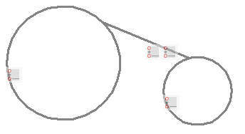
Coincident constraints between the endpoint of a line and two circles.
If the endpoints or center points of entities already coincide, the Autoconstrain option of the GCCOINCIDENT command automatically applies coincident constraints to such points.
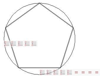
By applying coincident constraints between the pentagon vertices and the circle, and equal constraints between one side and the four other sides, the circle radius defines the size of the pentagon.
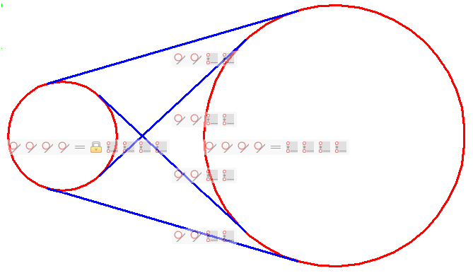
Coincident constraints between the endpoints of the tangent lines and the circles prevent the tangent lines to extend beyond the tangent points.
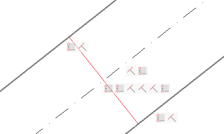
Coincident constraints are used to:
- Force the endpoints of the red line to lie on the bold lines.
- Force the midpoint of the red line to lie on the dash-dot line.
The bold lines and the dash-dot line have a perpendicular constraint with the red line. As a result the dash-dot line always lies centered between the two bold lines.