Workflow for OPTIMIZE, OVERKILL and SIMPLIFY commands
Context
The operation of exporting data from some 3D software and importing it to 2D many times might result in entities that are angled, overlapped and having gaps between them.
Example
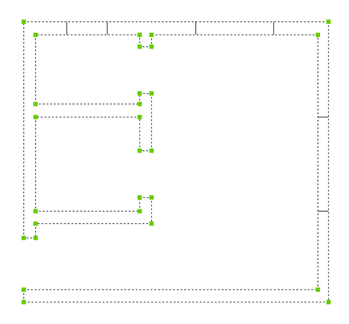
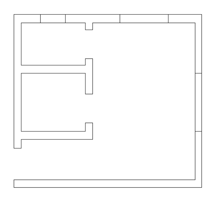
Here is a simple room plan as it was exported from a 3D and imported in 2D drawing. Due to incompatibilities of the software programs involved in the export / import operations, there are some lines that are angled, broken or overlapped.
Using a workflow that includes the commands OPTIMIZE, OVERKILL and SIMPLIFY, the plan can be improved.
Optimizing the lines
The command OPTIMIZE is used to straighten the lines.
Depending on the complexity of the input drawing and the quality of the import operation, there might be required to use this command many times.
In this case, there are many angled lines, overlapped lines and some gaps between them.
For the first run of the OPTIMIZE command, the parameters are:
- Selection: all the lines that are shown in the image.
- Close gaps: not checked.
- Reference angles: horizontal and vertical.
- Angle tolerance: 6 degrees.
- Distance tolerance: 50 mm.
See the command OPTIMIZE for more information.
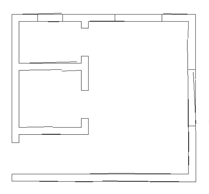
As shown in the image below, the result is better than the original drawing.
To further improve the quality of the geometry, the command could be run again.
For the second run of the OPTIMIZE command, the parameters are:
- Selection: all the lines that are shown in the image.
- Close gaps: checked.
- Reference angles: horizontal and vertical.
- Angle tolerance: 1 degree.
- Distance tolerance: 50 mm.
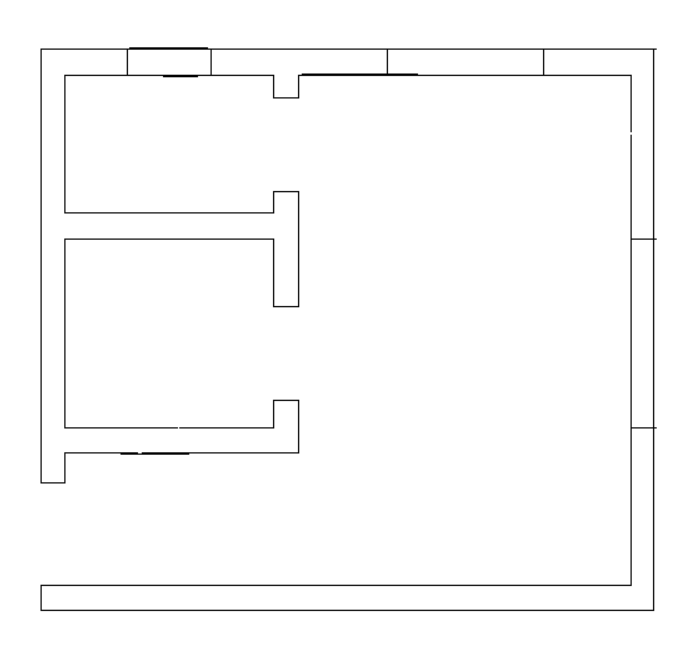
The drawing has improved considerably and also the gaps have been closed.
The next step is to further clean up the drawing.
Deleting duplicates and joining contiguous entities
The OVERKILL command allows to:
- Delete duplicated and overlapped entities.
- Straighten the angled entities
- Join partly overlapping or contiguous entities.
Running the OVERKILL command with a tolerance of 1 mm will achieve all the tasks above.
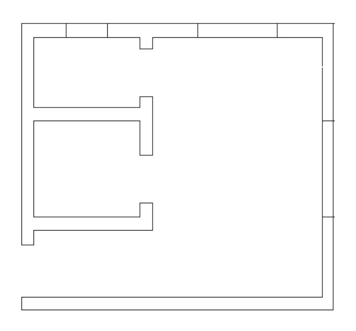
At this stage, the drawing has been cleaned up. There are no more angled or duplicated or overlapped lines. Also, the gaps have been close.
Simplifying the drawing
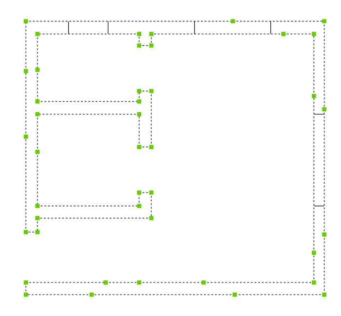
After joining the lines representing the walls into a single polyline, this one will have too many vertices. See the image below.
To remove the unnecessary vertices, the SIMPLIFY command is used.
The steps to applying this command are:
- Start the command.
- Choose the Simplify method.
- Choose the Max angle and distance option.
The parameters for the command are:
- Maximum distance between non-collinear vertices to straighten: 1
- Maximum change (angle) in a direction between each two consecutive segments to straighten: 1
- Straighten polyline arc segments? No
As shown, all the unnecessary vertices have been removed.