When you attach a point cloud that requires pre-processing, it converts 5 to 8 times
faster in BricsCAD® V22 compared to
V21.
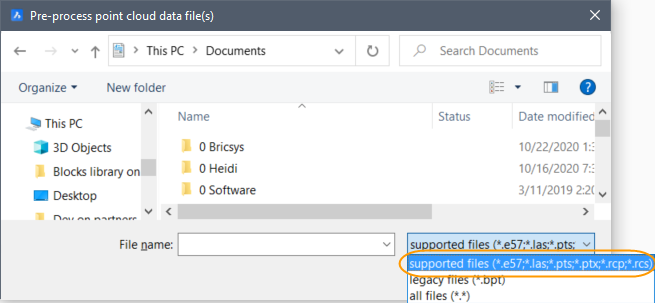
To pre-process a point cloud, you can use the POINTCLOUDATTACH command or Point
Cloud Reference Manager which is opened with POINTCLOUDREFERENCE
command.
You can find the log file in
C:\Users\USERNAME\AppData\Roaming\Bricsys\BricsCAD\V22x64\en_US\PointCloudCache\Folder_for_processed_pointcloud,
only if this path is set in the POINTCLOUDCACHEFOLDER system variable. Inside this
folder, you can view the current state of processing.
Note: The log file is more useful for troubleshooting, while
Point Cloud Reference Manager is the dedicated location to monitor
pre-process progress.
Note: Some unusual point cloud input files, like LAS files
with non-standard column layout or non-standard geo tags, are not automatically
preprocessed correctly. However, there is also a shell executable pre-processor
(preprocessor.exe) in the BricsCAD® installation folder that
allows to specify non-standard column layout and/or geo tags (-w skip). The
shell pre-processor uses the same library under the hood, but it exposes some
manual options that are not automatically used by BricsCAD®. To learn about the
options, run the pre-processor executable without arguments in an OS shell. A
usage summary will be printed. For more detailed information see the How to
use the preprocessor.exe in order to ignore GeoTIFF tags while preprocessing
non standard .LAS, .LAZ pointcloud data?
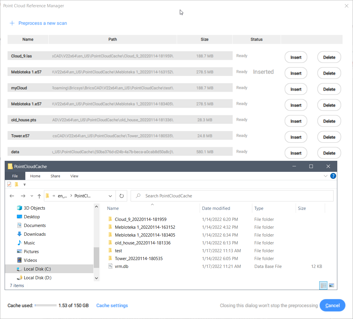
Note: Any subfolder with previously pre-processed point cloud
cache data (from another BricsCAD point cloud cache folder or preprocessed with
the shell executable preprocessor.exe) can be copied in the folder specified by
the POINTCLOUDCACHEFOLDER system variable (default value:
C:\Users\USERNAME\AppData\Roaming\Bricsys\BricsCAD\V22x64\en_US\PointCloudCache)
and will be available next time you will open the Point Cloud Reference
Manager. For each subfolder in the point cloud cache folder, there is an
item in the reference dialog box:
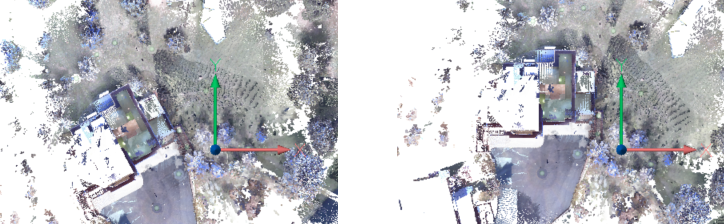
Alignment
The POINTCLOUDALIGN command automatically rotates a point cloud to optimally align it
with the X and Y axis (the points must be in vertical planes (e.g. walls). To
determine the best alignment, it can analyze the entire point cloud, or you can
specify the most relevant area.
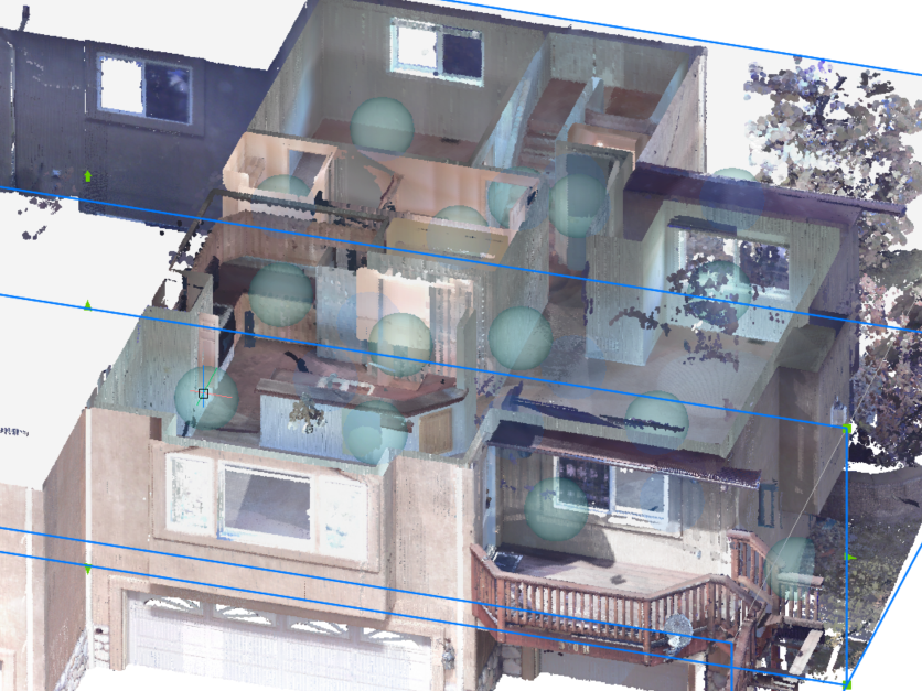
Bubble Viewer
The point cloud displays
bubbles at all the scan locations if:
the data was captured from a set of fixed scan positions (stand somewhere
fixed and capture millions of scanned points from a single origin scanner
location);
the data format allows to store that info.
In these locations, you will experience the most realistic visual
representations.
Example of situation when either (1) or (2) is not satisfied:
Mobile mapping (scanning for example while walking around, or from
airplanes) has no fixed scan positions, thus has no bubbles.
Also certain file formats like las have no possibility to store scan
positions, even when the data was captured from fixed scan positions. So
then also no bubbles can be created
Note: Point cloud bubbles are only created when points are
scanned with static scanners and points are grouped per scanner location. LAS
and PTS files do not contain scanner information, so they cannot produce point
cloud bubbles.
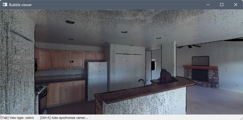
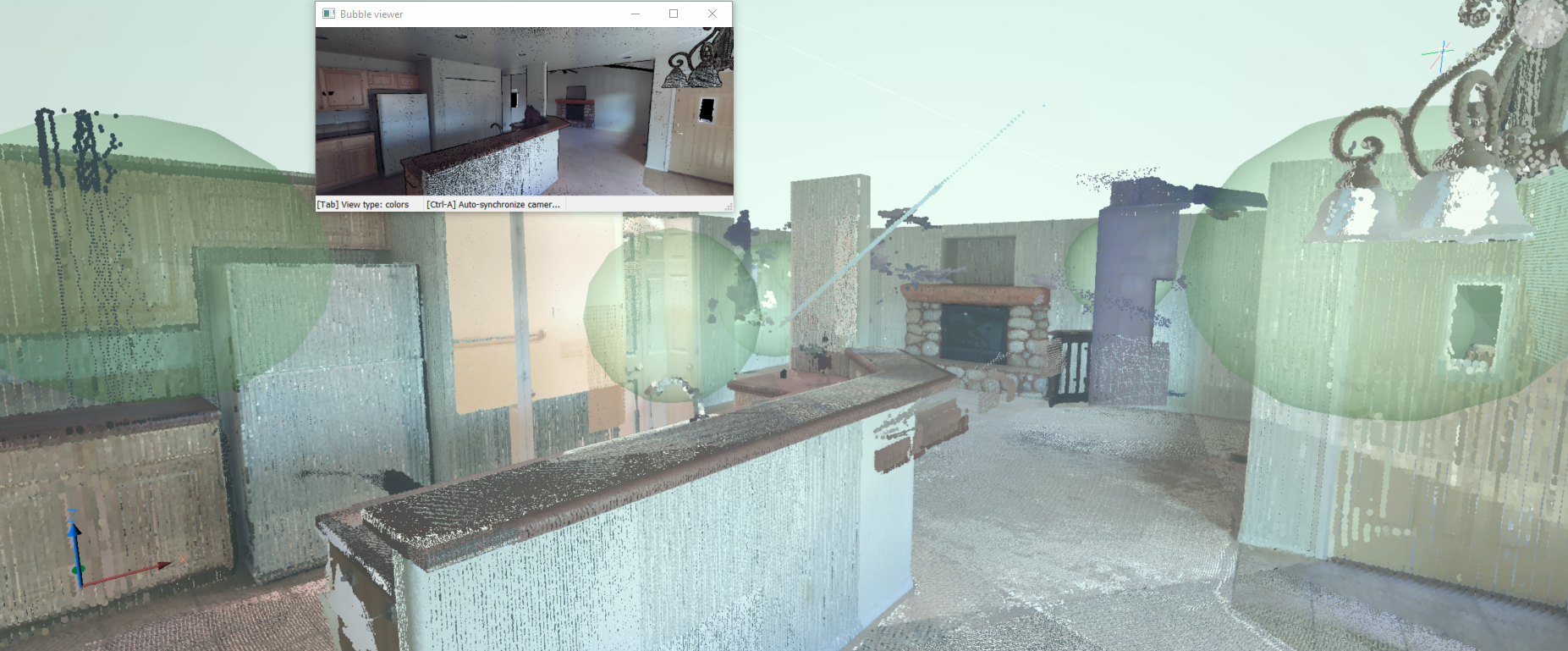
Double-click one of the bubbles in model space to open the Bubble viewer. You can
press the middle mouse button and move the mouse to view the point cloud in any
direction from that scan location. You can also zoom in and out using the mouse
wheel.
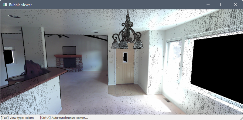
Press the Tab key to cycle through three different visual modes.
The first
mode displays the points as their actual colors or in grayscale, depending how the
data was scanned.
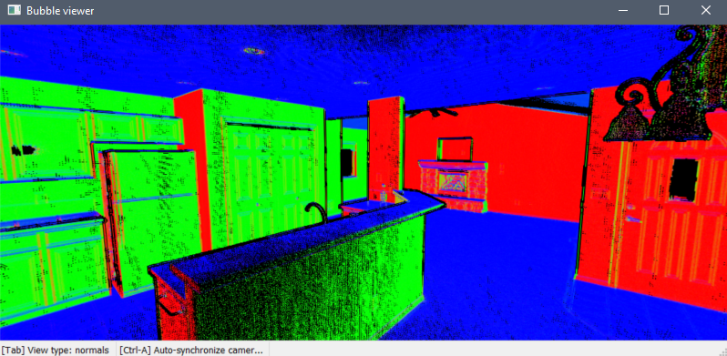
The second mode displays the points as red, green, or blue
according to their normal vectors. The colors correspond to the UCS axes.
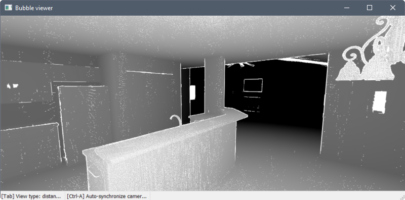
The third mode displays the points from light to dark as the distance
from the scan location increases.
You can easily sync the drawing view to match the Bubble viewer by
pressing Ctrl+A.
Note: You can turn off point cloud bubbles
from Model Space and you can change their size in the Properties panel.
Entity snaps
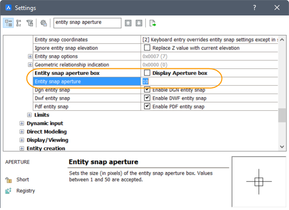
The Point Cloud Nearest Point entity snap significantly improves the ability to
select relevant point cloud points. It uses an imaginary cylinder from the current
viewpoint toward the cursor.
The radius of the imaginary cylinder is defined by the Entity snap aperture box
setting.
Note: The result is the point in the imaginary
cylinder that is the closest to the camera.
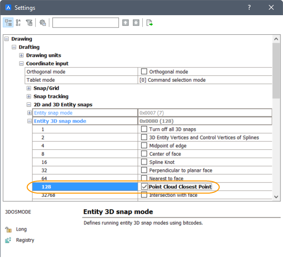
Enable the new Point Cloud Nearest Point entity snap together with other 3D entity
snaps in the Entity Snap menus, toolbar and settings.
Note: Make sure that only the 128 bitcode of the 3DOSMODE system variable is
set.
Export
The POINTCLOUDEXPORT command allows you to export a cropped selection of a point
cloud to a PTS file.
Floor Detection
SectionPlanes work on point clouds as well. You can use them to show parts of point
clouds. The difference between point cloud crops and SectionPlanes is that point
cloud crop only clips the point cloud while section planes clip all geometry in your
drawing.
The POINTCLOUDDETECTFLOORS command generates volume sections for each floor found in
a point cloud representing a building. The detection is based on regions of points
with similar Z-coordinates. The generated volume sections can help in navigating
point clouds of buildings.
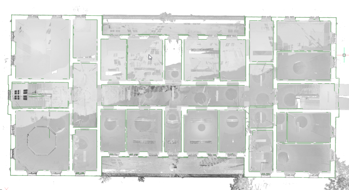
Point cloud projection
The POINTCLOUDPROJECTSECTION command enables you to detect walls from the volume
section of a point cloud based on a variety of wall detection options. You can
create volume sections automatically for each floor in a building. You can use these
sections to generate 2D lines to create a 2D floorplan or a vertical section. This
is a background process and multiple sections can be processed in a queue. This way,
it is possible to run this command in full resolution on all sections.
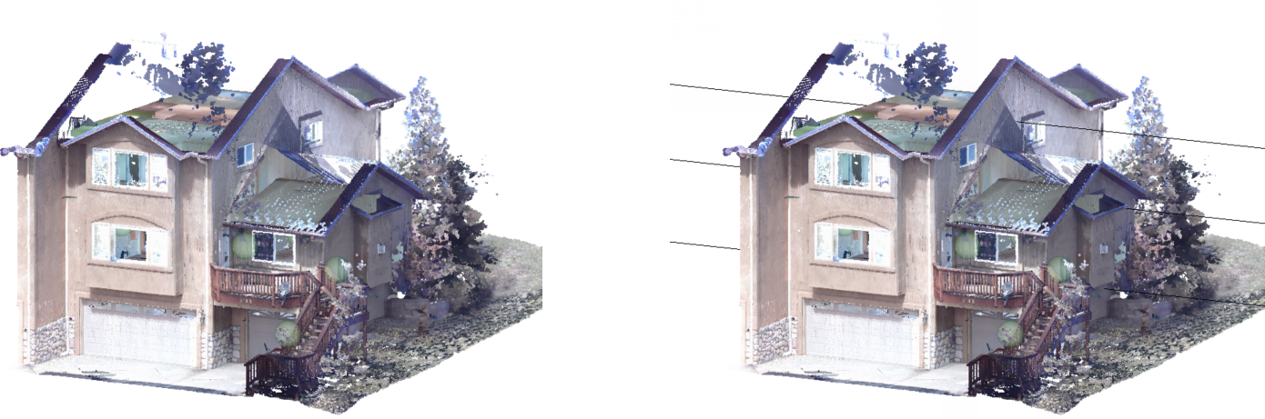
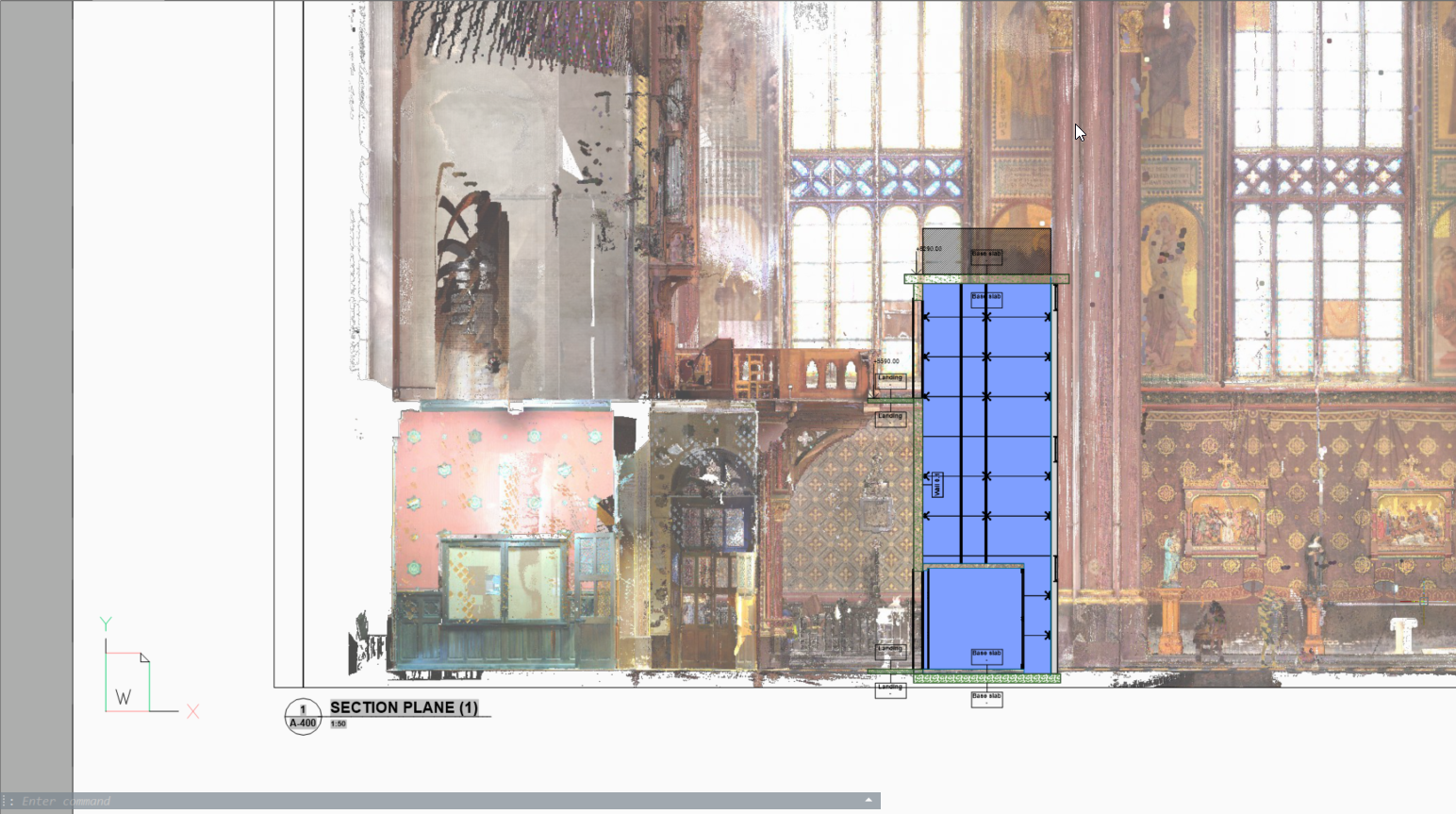
At the same time, a raster image is generated to give the user some context. In some
cases, it is not necessary to recreate the existing building. Background images can
give much more context to the design documents. These can be used to verify the
created 2D geometry but in high quality scans, these images can also be used as
graphical material. For example, as a background image for a BIM model in renovation
projects where modern intervention are made in historical buildings.
Planar Fit
The POINTCLOUDFITPLANAR command enables you to create 3D geometry based on the point
cloud. It will create a planar surface or solid after selecting one point in a point
cloud. The points that seem to be in a plane are never exactly in one plane,
therefore a threshold value is set as a property of the point cloud entity. This
also works in bubble view.
Note:
Select openings allows to take into account the openings of doors and
windows.
Adjust borders allows to adjust the planar border contour.
Stitch surfaces provides stitching the result of multiple fitted planes
into, for example, a solid which can be later used with the BIMINVERTSPACE
command.
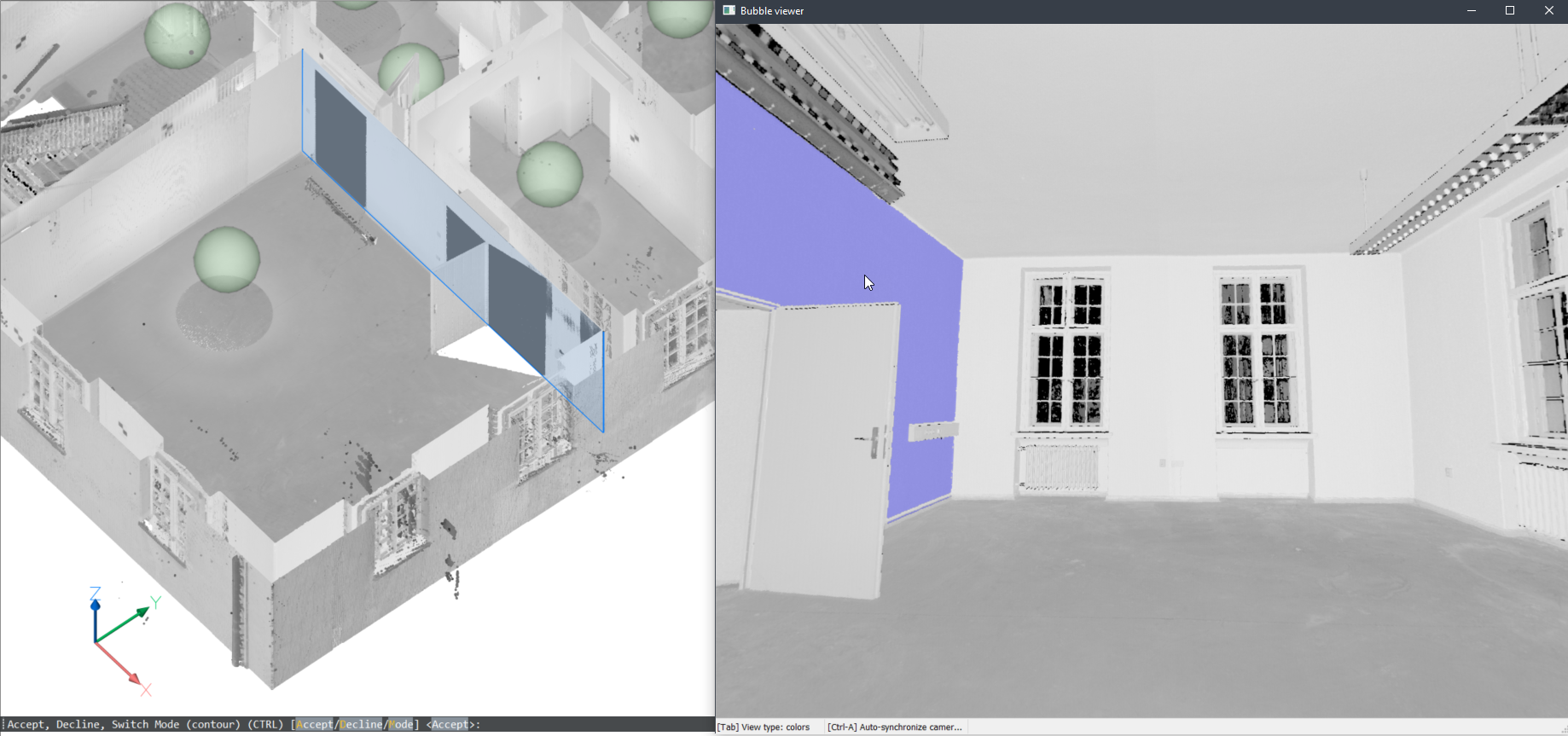
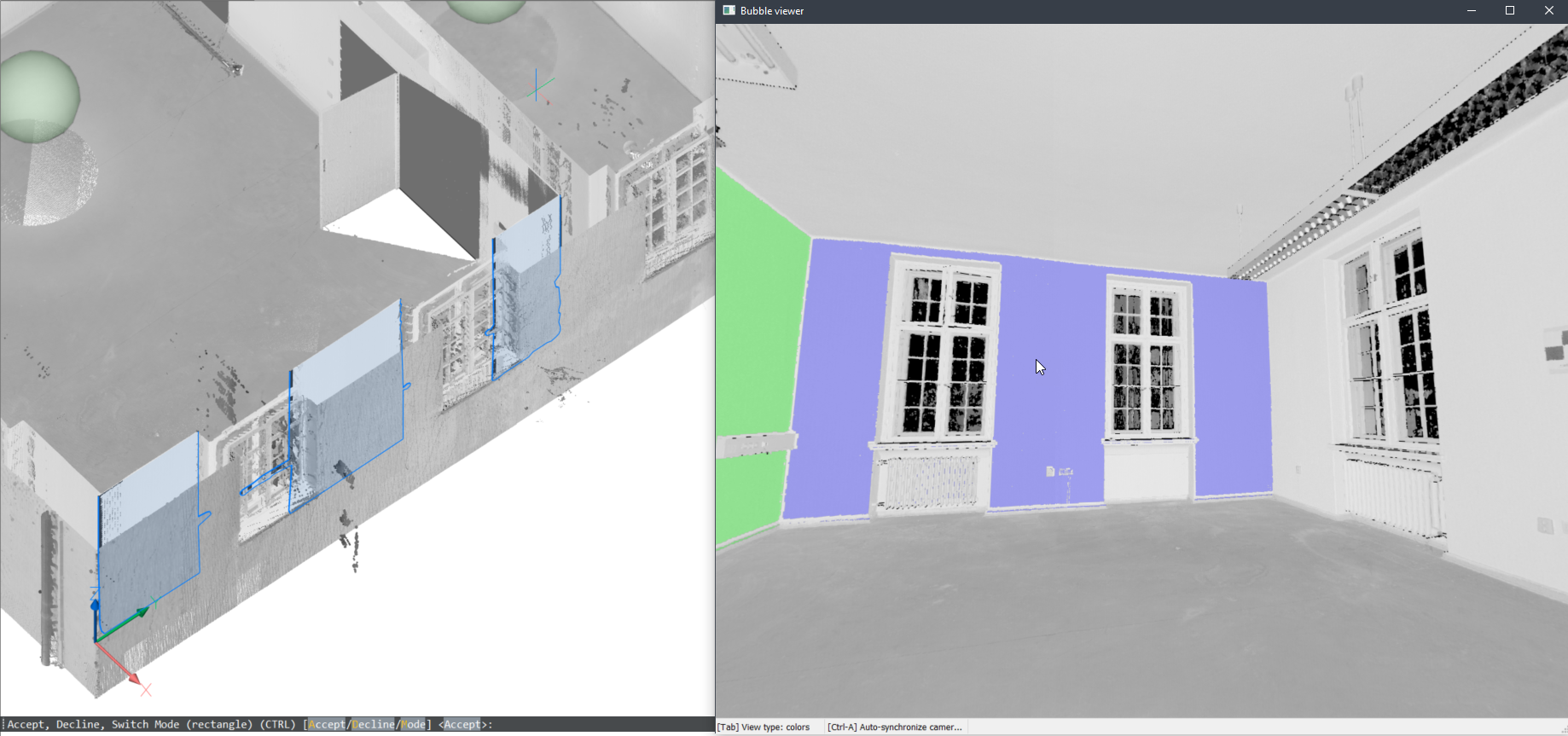
In bubble view
If the bubble viewer is open before launching the command, BricsCAD® expects you to select plane
seed points in the bubble viewer. The cursor will give you a preview of the normal
direction of the plane. Next, you get a preview in both bubble view and model view.
You can toggle between 2 shape representations using the CTRL key.
Note: While still in selecting mode, the corresponding points in
bubble are shown in purple. These points are shown in green once the user
accepts the generated result.
In model space
You can also use this command in the model space when the bubble viewer is not open.
BricsCAD® will ask you to select a
point of the point cloud in model space. Depending on the size of the cropped point
cloud, it takes more time, but it has 2 advantages by searching multiple scan
positions:
It can create larger surfaces where only parts are visible in each scan
position.
It can detect wall and slab thickness since it can take the opposite surface
into account.
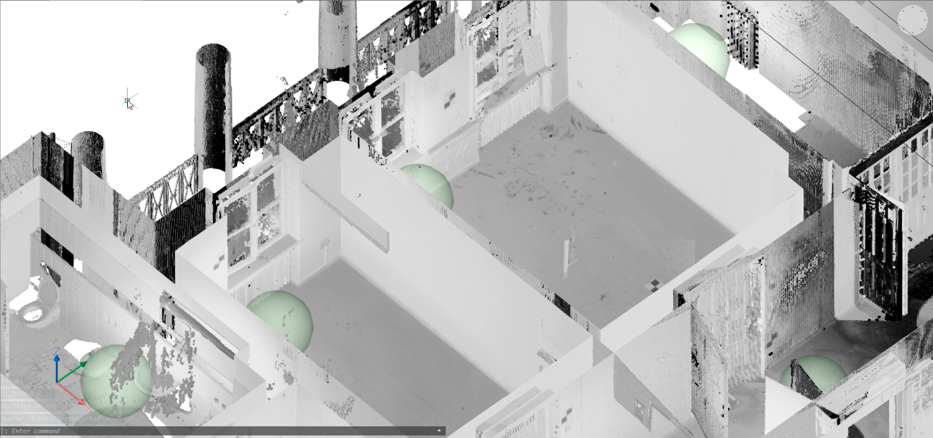
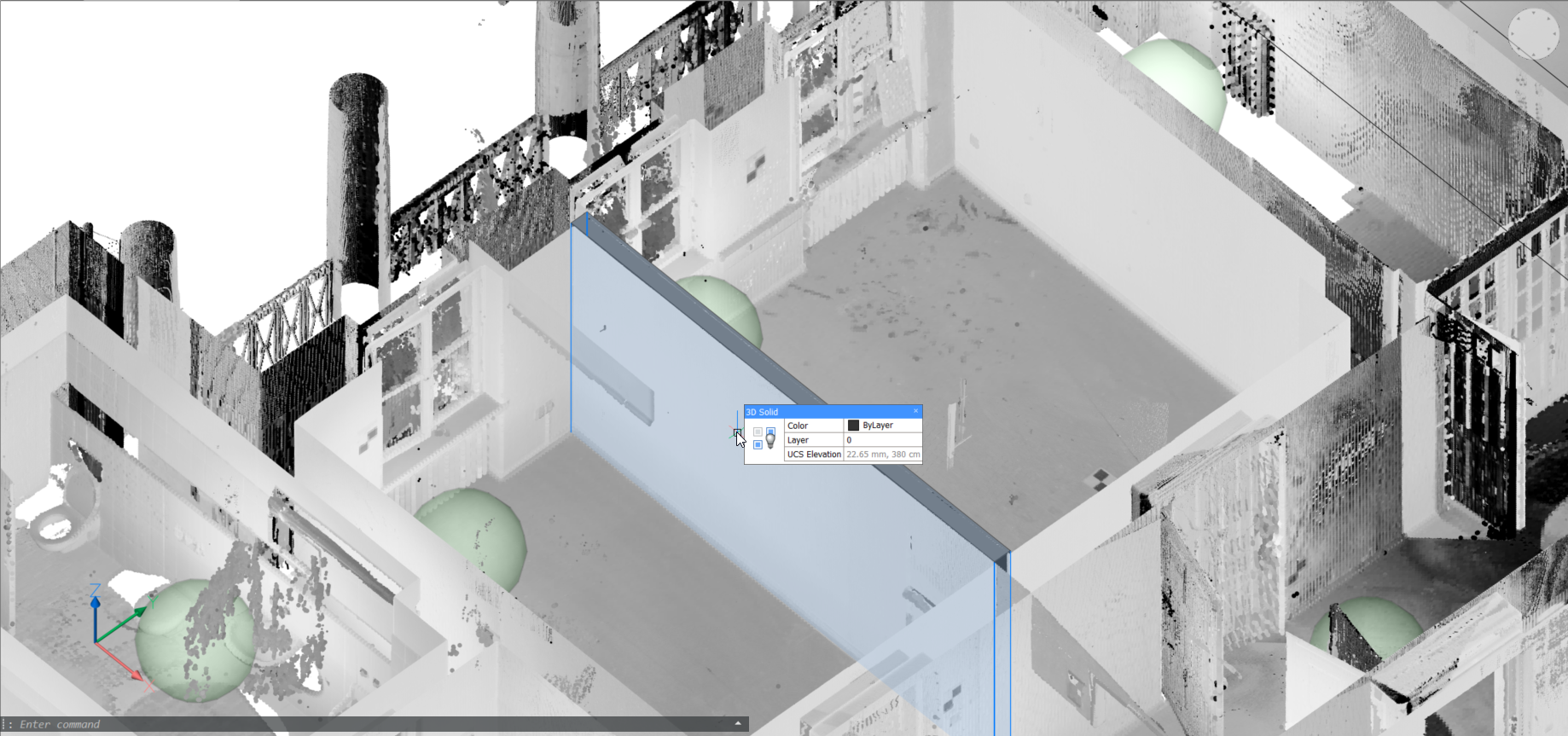
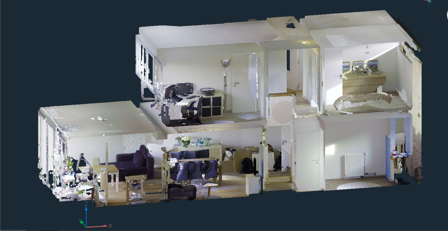
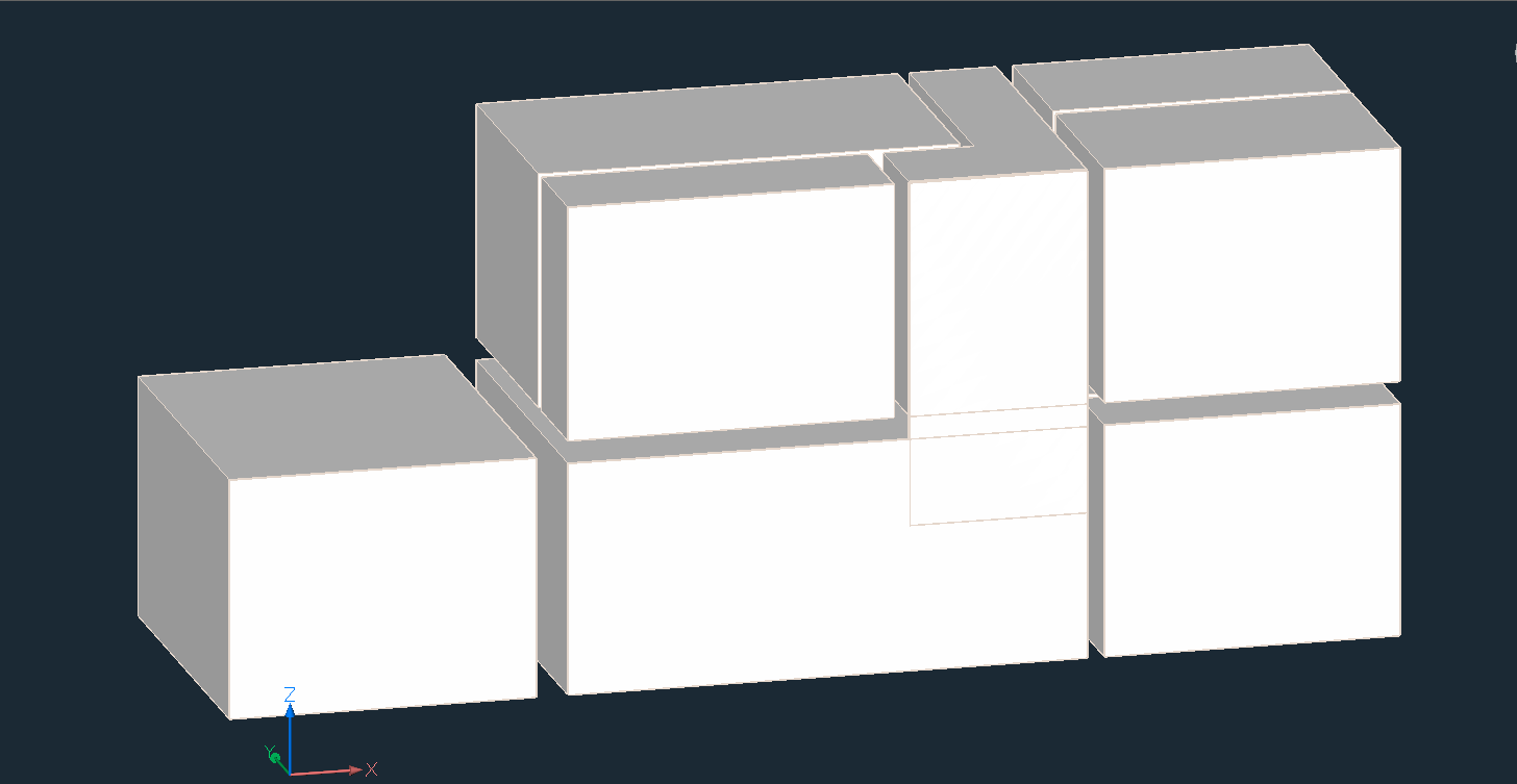
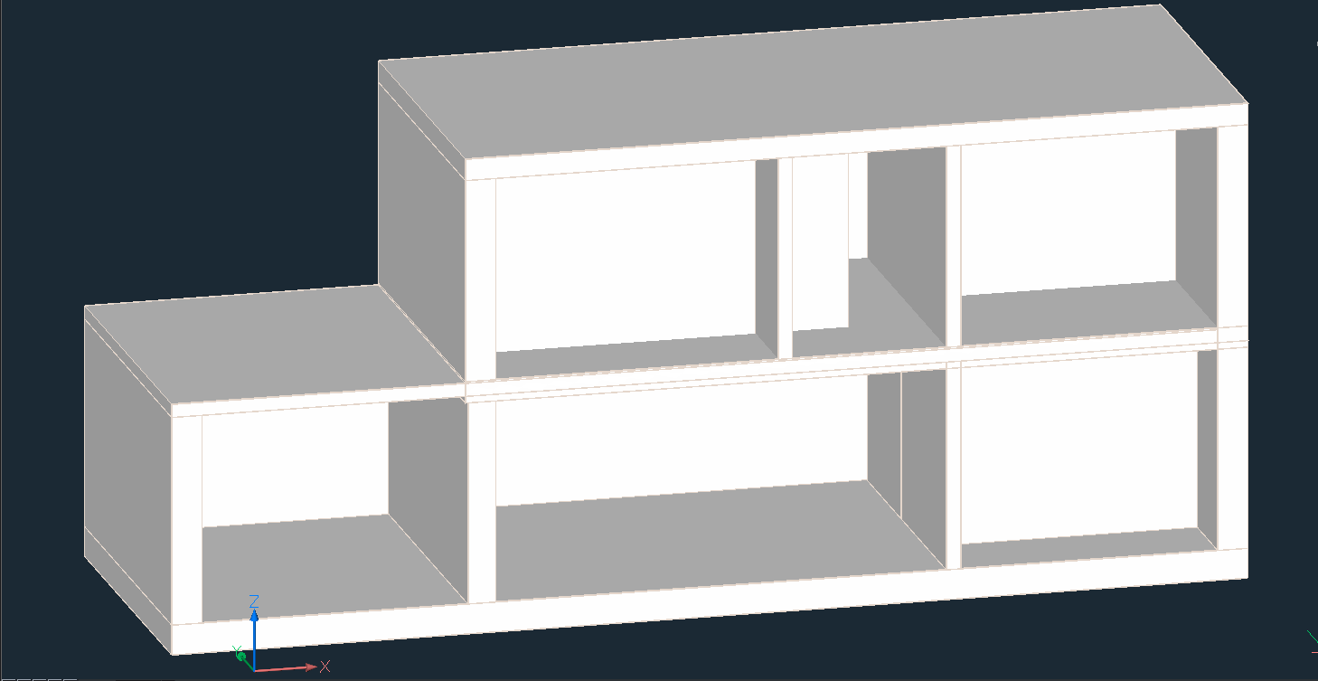
Note:
Workflow in which a point cloud (top image) is first converted to a set
of solids, one per room, using stitched fitplanar results (middle
image). The command BIMINVERTSPACES converts these temporary room solids
into a building model with walls and slabs from the inversion of these
solids.
Fitplanar in bubbles allows you to add openings (doors, windows), and
adjust the resulting contour.
You can use bubbles to use snap points to draw things like
(poly)lines.
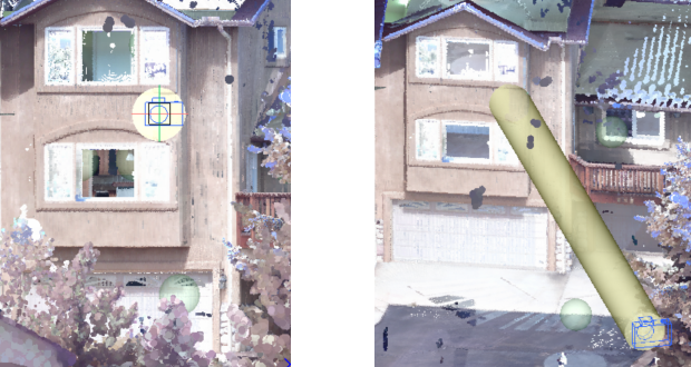
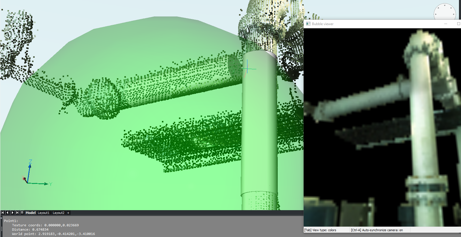
Fit cylinder in bubbles:
Bubble view window on the right, model space on the left. Two
clicks along the cylinder axis in bubble space are needed to
extract a cylinder (results as solids in model space). This is a
first version of the algorithm, and will be made more robust in
the near future.
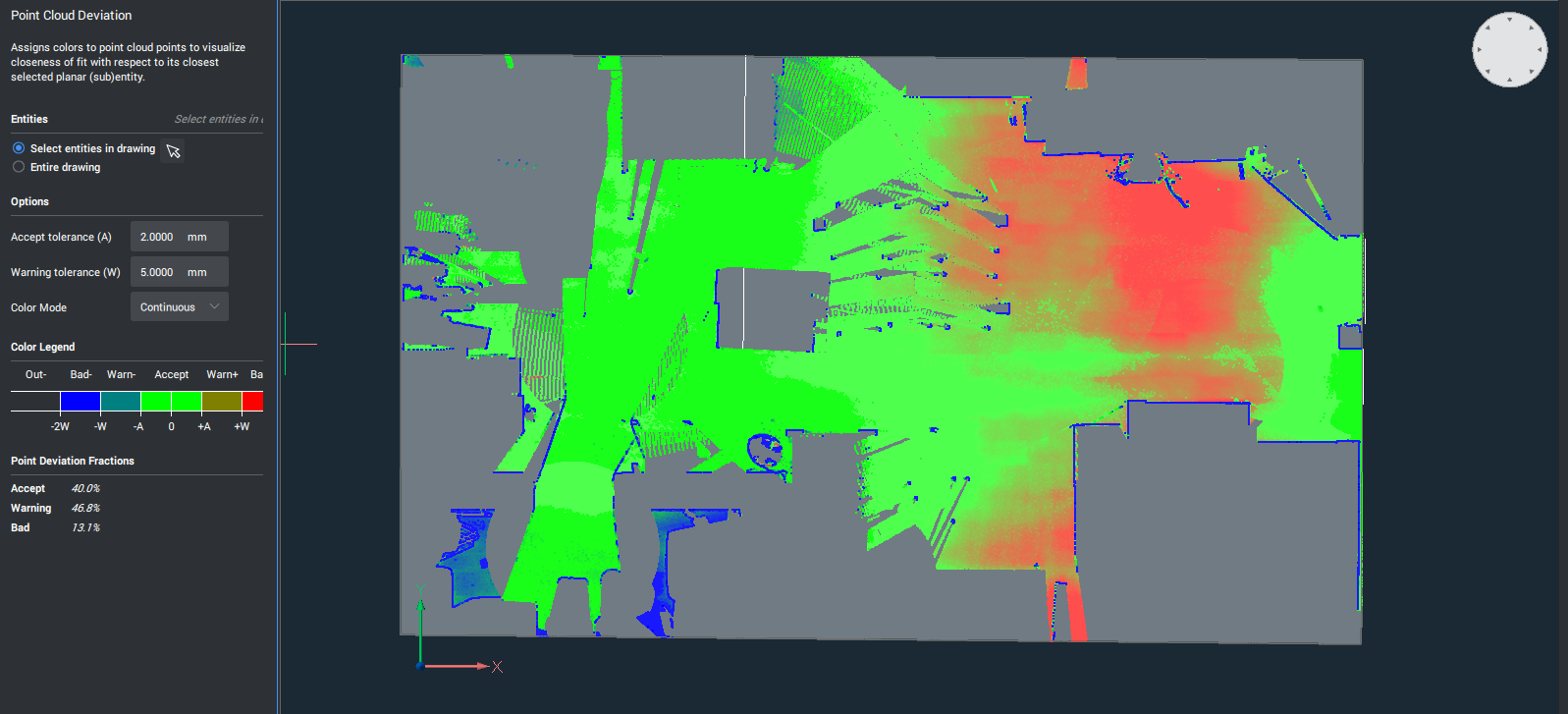
The POINTCLOUDDEVIATION allows you to visually assess the fit between
planar structures and points of the point cloud.
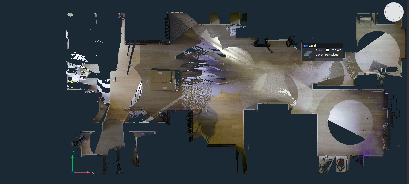
Point cloud section of floor of a house:
Visualization of distances of points from floor plane. In the
left panel, an explanation of the colors is provided (green is
planar, gradient from green to blue here is further above the plane,
gradient from green to red is further below the plane). Also, a
summary of the percentages of points in which category is presented
(OK, warning level, …)