


Customizing BIM quantities
About
Entities have a set of properties which can be viewed in the Properties Panel. If an entity has been assigned a certain BIM classification or Type (e.g. Wall or Slab), additional properties will be displayed such as IFC Common properties and Base quantities. Which properties are displayed in the panel is managed in the BIM Properties dialog box, which is opened by the BIMPROPERTIES command.
Namespaces
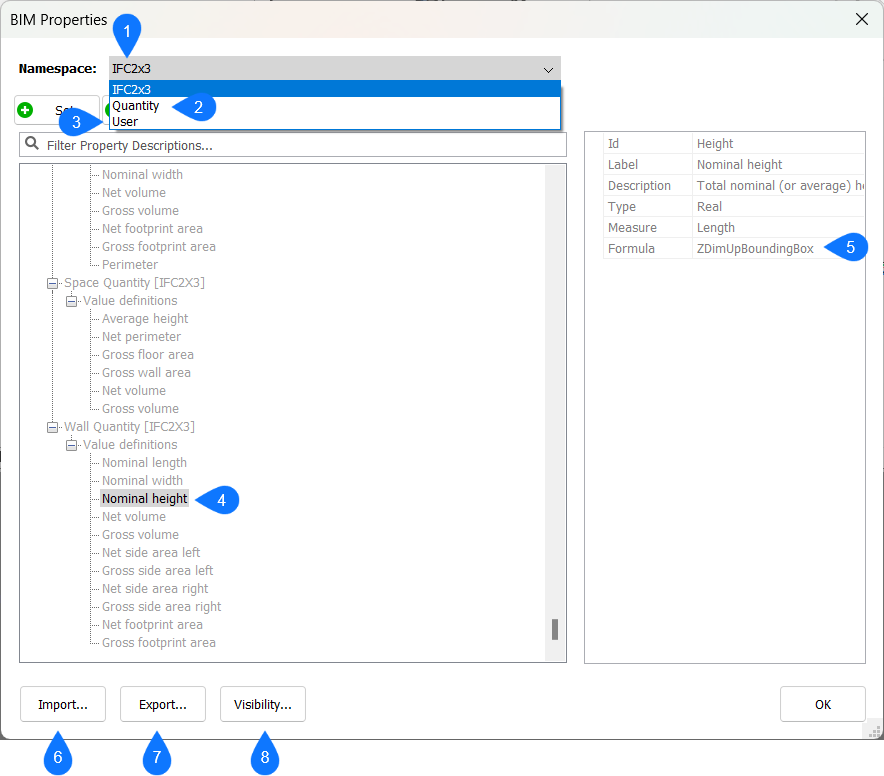
In the BIM Properties dialog, by default three namespaces are available: IFC2x3 (1), Quantity (2) and User (3). The IFC2x3 namespace contains properties that are defined by the IFC2x3 schema. This contains both common properties (e.g. Wall Common properties, such as Fire Rating and Acoustic Rating), and Quantities (e.g. (4)). These Quantities are based on so-called Core quantities (5) of the solid. See Core quantities for more information.
The User namespace exists for the user to create their own property definitions. See also the Procedure article Custom Properties for more information on custom properties.
It is also possible to import namespaces, e.g. the IFC4 namespace. This can be done by clicking the Import button (6) on the bottom left.
You can export all property sets (properties/quantities) defined in the drawing to an XML file by clicking the Export button (7) on the bottom left. You import this file in another drawing.
The visibility of namespaces or attribute sets can be toggled on and off according to your preferences by clicking the Visibility button (8).
Core quantities
Core quantities are quantities of solids that are calculated based on the geometric features of that solid, and that can be used in user-defined quantities. These core quantities are also the basis for the quantities defined in the IFC2x3 and IFC4 properties as described in the previous section.
| Core Quantity | Description | Measure | Type |
|---|---|---|---|
| NumberOfPlies | Number of plies in the attached composition. | Integer | |
| XDimUpBoundingBox | X dimension of the bounding box found with global Z axis rotation freedom. | Length | Real |
| YDimUpBoundingBox | Y dimension of the bounding box found with global Z axis rotation freedom. | Length | Real |
| ZDimUpBoundingBox | Z dimension of the bounding box found with global Z axis rotation freedom. | Length | Real |
| XDimFreeBoundingBox | X dimension of the bounding box found with 3D rotation freedom. | Length | Real |
| YDimFreeBoundingBox | Y dimension of the bounding box found with 3D rotation freedom. | Length | Real |
| ZDimFreeBoundingBox | Z dimension of the bounding box found with 3D rotation freedom. | Length | Real |
| DistanceBetweenMajorSurfaces | Distance between major surfaces. | Length | Real |
| FirstMajorSurfacePerimeter | Perimeter of the first (largest) major surface. | Length | Real |
| SecondMajorSurfacePerimeter | Perimeter of the second major surface. | Length | Real |
| LinearAxisLength | Length of the linear element's axis. | Length | Real |
| VariablePlyThickness | Thickness of a variable ply. | Length | Real |
| FirstMajorSurfaceNetArea | Area of the first (largest) major surface after subtracting openings. | Area | Real |
| FirstMajorSurfaceGrossArea | Area of the first (largest) major surface before subtracting openings. | Area | Real |
| SecondMajorSurfaceNetArea | Area of the second major surface after subtracting openings. | Area | Real |
| SecondMajorSurfaceGrossArea | Area of the second major surface before subtracting openings. | Area | Real |
| IsMajorSurfacesParallel | Indicator if the major surfaces are parallel. | Boolean | |
| TotalSurfaceNetArea | Area of the solid's surfaces after subtracting openings. | Area | Real |
| TotalSurfaceGrossArea | Area of the solid's surfaces before subtracting openings. | Area | Real |
| FootprintNetArea | Area of the bottommost solid's surfaces after subtracting openings. | Area | Real |
| FootprintGrossArea | Area of the bottommost solid's surfaces before subtracting openings. | Area | Real |
| ProjectedNetArea | Area of the solid's surfaces projected to global XY plane after subtracting openings. | Area | Real |
| ProjectedGrossArea | Area of the solid's surfaces projected to global XY plane before subtracting openings. | Area | Real |
| CrossSectionNetArea | Area of the cross section for linear elements after subtracting openings. | Area | Real |
| OuterSurfaceNetArea | Area of the outer surface for linear elements after subtracting openings. | Area | Real |
| NetVolume | Volume of the solid after subtracting openings. | Volume | Real |
| GrossVolume | Volume of the solid before subtracting openings. | Volume | Real |
User-defined quantities
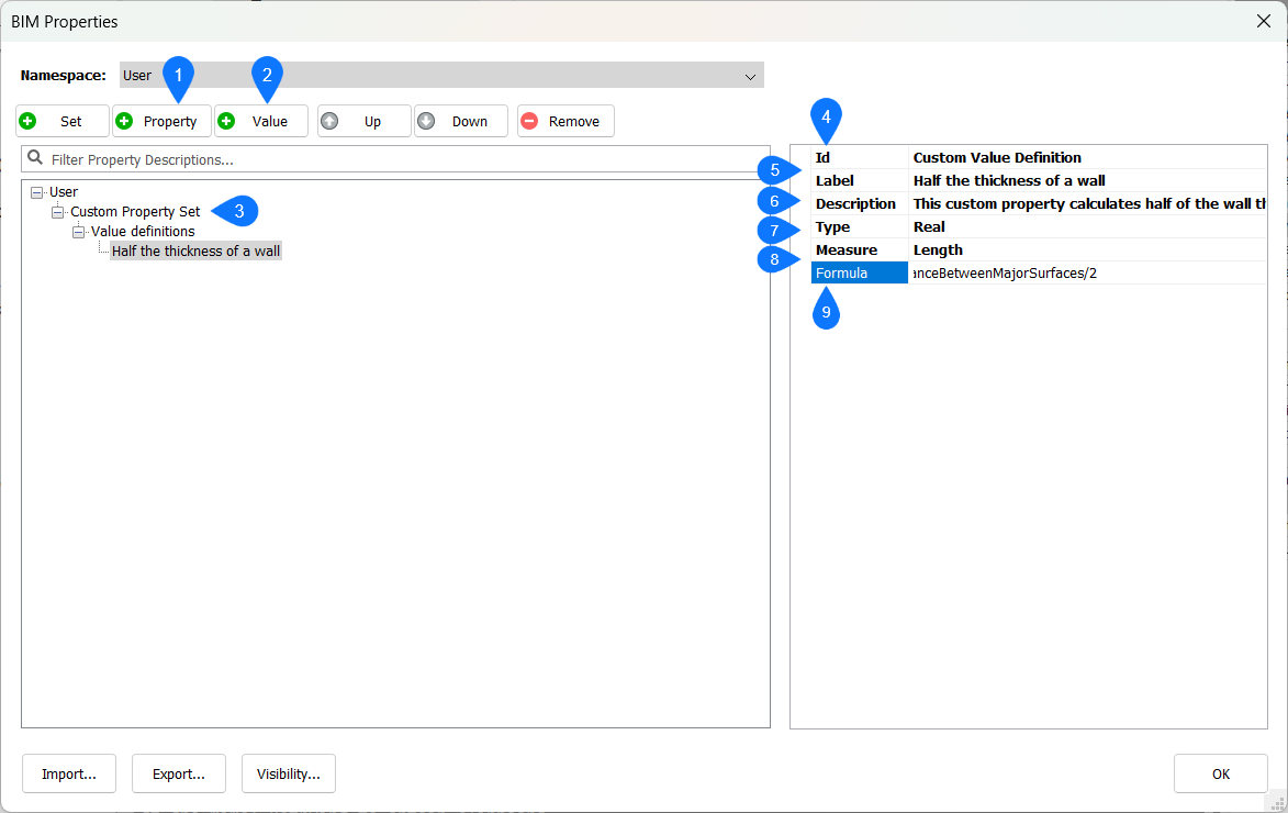
In the User namespace it is possible to create custom properties inside a custom property set using the Property (1) button, see the Procedure article > Custom Properties.
- Id (4): a unique identifier.
- Label (5): the name of quantity which will show up in the properties panel. This can be the same as the ID, however the ID must be unique.
- Description (6): a description of the quantity.
- Type (7): the type of the quantity. Typically, a quantity will be defined as a Real value.
- Measure (8): the measure of the quantity, i.e. is it a length value, an area, volume or mass?
- Formula (9): the actual expression of the quantity. Here Core quantities can be used, as well as mathematical expressions as defined in the Procedure article Working with Parameters and Constraints.
In this example, a user-defined quantity is defined that displays half the thickness of a wall, which is calculated as DistanceBetweenMajorSurfaces/2.
Procedure: creating a user-defined quantity
In this part you will learn how to make user-configurable quantities. By way of example, we will define a quantity of Spatial objects such as a room. The quantity will be the Compactness which can be calculated as the volume of the space divided by the sum of the areas on all sides of the space.
- Open the BIM Properties dialog box by typing BIMPROPERTIES in the Command line.
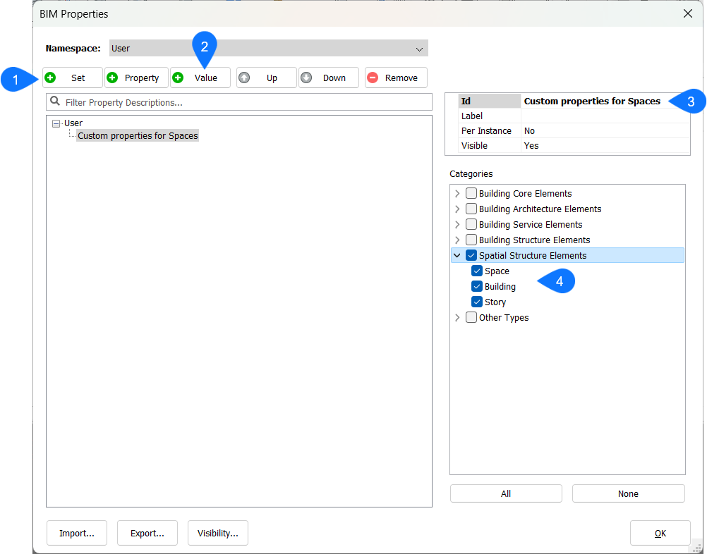
- Set the User namespace as current namespace.
- Create a new Property Set by clicking the Set button (1), and give it a name (3).
- Assign the Property Set to one or more categories (4). In this example we will assign it to spatial elements.
- Create a new Value Definition by clicking the Value button (2).
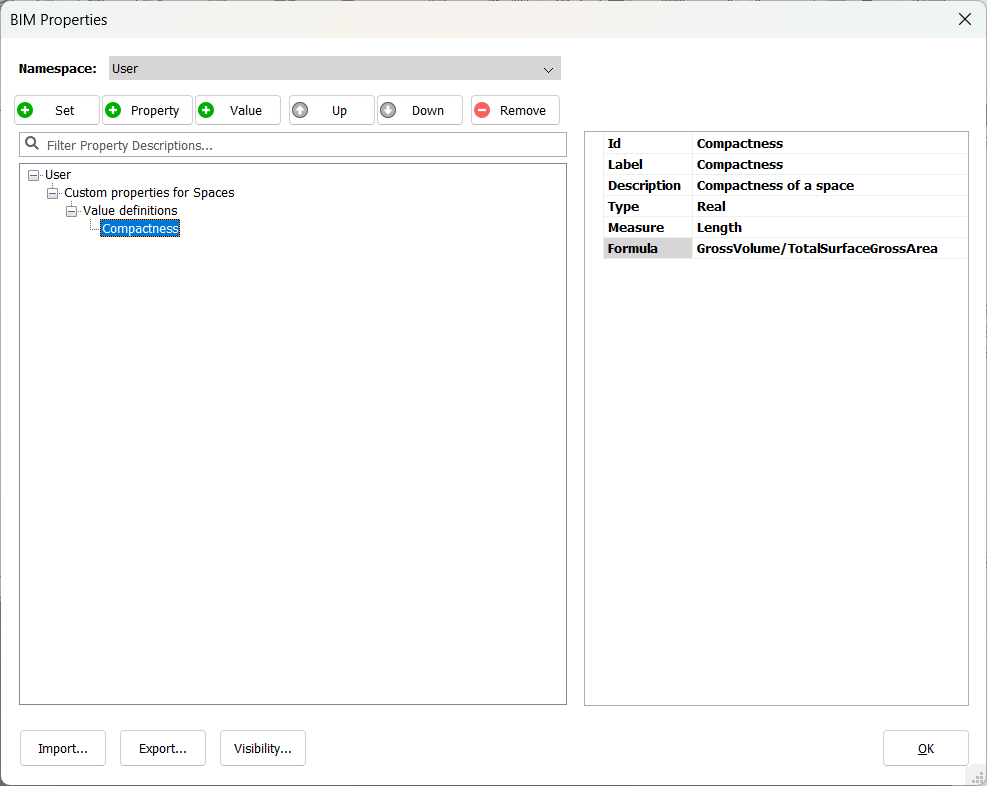
- Give this Value Definition an Id and a Label, e.g. Compactness.
- (Optional) Give this Value Definition a description.
- Assign the correct Type to this Value Definition. Because our Value Definition will be based on a calculation of two Real values, this will also be a Real value.
- Assign a Measure to the Value Definition. Because the result of the calculation will be a volume divided by an area, we will end up with a Length measure.
- Fill in an expression in the Formula field. The volume of a space is a Core quantity with the name GrossVolume. The sum of areas of the space on all sides is also a Core quantity with the name TotalSurfaceGrossArea. Hence, we can define the Compactness = GrossVolume/TotalSurfaceGrossArea.
- Click OK to close the BIM Properties dialog box.
- Create a volume that represents a space, either by creating surrounding elements like walls and a slab, and by defining a space inside using the BIMSPACE or BIMIFY commands, or by creating a solid and using BIMCLASSIFY to classify it as a Space.
- Select the space. In the BIM Properties panel you should now see your user-defined property under a separate property set:
