


Interference checking
About interference checking
The Interference Checking tool is used during the modeling phase to find out conflicts in the model by comparing 3D solid models of building elements. Interference occurs when two 3D entities overlap in 3D space. In BricsCAD BIM, the Interfere tool helps you to find intersections between the entities that you have selected. You can also do the interference checking for all elements in your model at a time. Optionally, the tool creates interference solids after running the command. The newly created solids are placed on their own layer, as specified by the INTERFERELAYER system variable. Running an interference check on existing models allows you to prevent the conflicts in your entire model.

For more information about this command, visit the Command Reference article INTERFERE.
Procedure: performing an interference check
- Select the desired 3D solids to be checked for interference, then launch the INTERFERE command.Note: Multiple solids can be selected using the selection box or in the Structure Browser, depending on whether the selected entities appear when selected in the tree.
The first set of entities is defined.
The Command line displays how many entities in total are set for interference checking e.g. Entities in set: 20.
Note that the Nested Selection option allows you to select 3D solid models that are inside blocks and external references (XRef) and once they are selected you can compare them against other entities in the selection set.
- Select the 3D solids in the model to add them to the second set of entities.
The entities in the first set are compared with the entities in the second set.
Note: If you press the Enter key without selecting any solids for defining the second set of entities, the entities in the first set will be compared to each other. - Press Enter to run the interference check.
- The interference volume is created for each collision and it is shown in a solid model.Note: The solids of the interference volume are displayed in red since they are placed on layer Interferences. The default settings on the Interference Checking tool makes it easy to find the intersecting solids in the model. This setting can be changed using the prompt menu or the Command line. To open it, click the Settings option in the prompt menu or type “S” while the interfere command is still active. The Interference Settings dialog box displays. The dialog box allows you to configure interference settings, which are stored in variables.
The following illustration shows the Interference Settings dialog box. The table below presents each component of the dialog box.
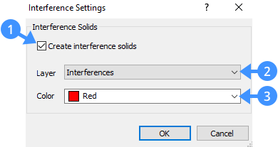
Create interference solids box (1) Determines whether a solid or region of the interference is created. Check to create a solid of the interference volume or region of the interference area.
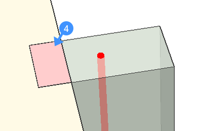
Layer (2) Shows the current layer for interferences. Color (3) Shows the current layer color. The following illustration shows the detected collision (4) between the floor slab and column.
- To remove the undesired intersections, turn off the Interferences layer, and use one of the 3D solid modifying tools e.g. BIM Drag or Subtract on the interfering solid. This process will let you make the necessary corrections in your model.
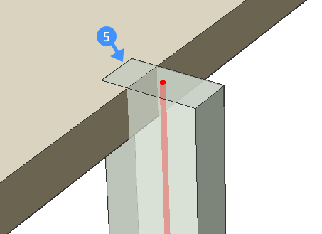
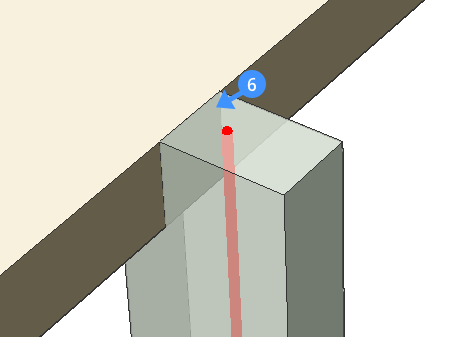
In the following illustration, the created solid of the interference volume is shown (5). In the second image, the intersection is fixed by subtracting the slab geometry from the column.
- Run the INTERFERE command a second time to check whether all interferences are fixed.
If there are no collisions left, the Command line reports that “Solids do not interfere”.