


Rhino/Grasshopper integration
About
Rhinoceros3D is a 3D modeler developed by Robert McNeel & Associates of Seattle, Washington USA. Rhino is used to create, edit, analyze, document, render, animate and translate NURBS (curves, surfaces, solids, point clouds and polygon meshes).
Grasshopper is a visual programming language environment that runs within the Rhinoceros 3D computer-aided design application. It is tightly integrated with Rhino's 3D modeling tools.
Installing Rhino/Grasshopper connection
- Download Rhino from here.Note: Users can use the Rhino/Grasshopper Connection within BricsCAD with trial license keys of both current version of BricsCAD BIM and Rhino 7. Since the release of BricsCAD V21, keys for older versions of Rhino will not work for this integration.
- Download the Grasshopper-BricsCAD Connection from the BricsCAD Application Store: BricsCAD Application Catalog. The installer copies all required files to the Program Files\Bricsys\Grasshopper-BricsCAD Connection folder.Note: The Grasshopper-BricsCAD Connection currently available from the Application Store will work in the current BricsCAD Pro, BIM, Mechanical or Ultimate versions.Note: The Grasshopper-BricsCAD connection works with Pro, Mechanical, BIM and Ultimate for creating geometry. However, the BIM specific functionality (adding classification, spatial locations, profiles, properties, IFC export) will only work with a BricsCAD BIM or a Ultimate license.
- Restart BricsCAD.
- To launch Grasshopper or Rhino, open and save a new drawing. Then use the buttons in the new tab that is displayed in the ribbon or launch with the Quad.
To launch a Grasshopper file from BricsCAD
- Open an empty BricsCAD file.
- Save it.
- Open Grasshopper with the button in the new Grasshopper tab inside BricsCAD.
- You can close the Rhino pop-up window. Rhino will continue to work in the background.
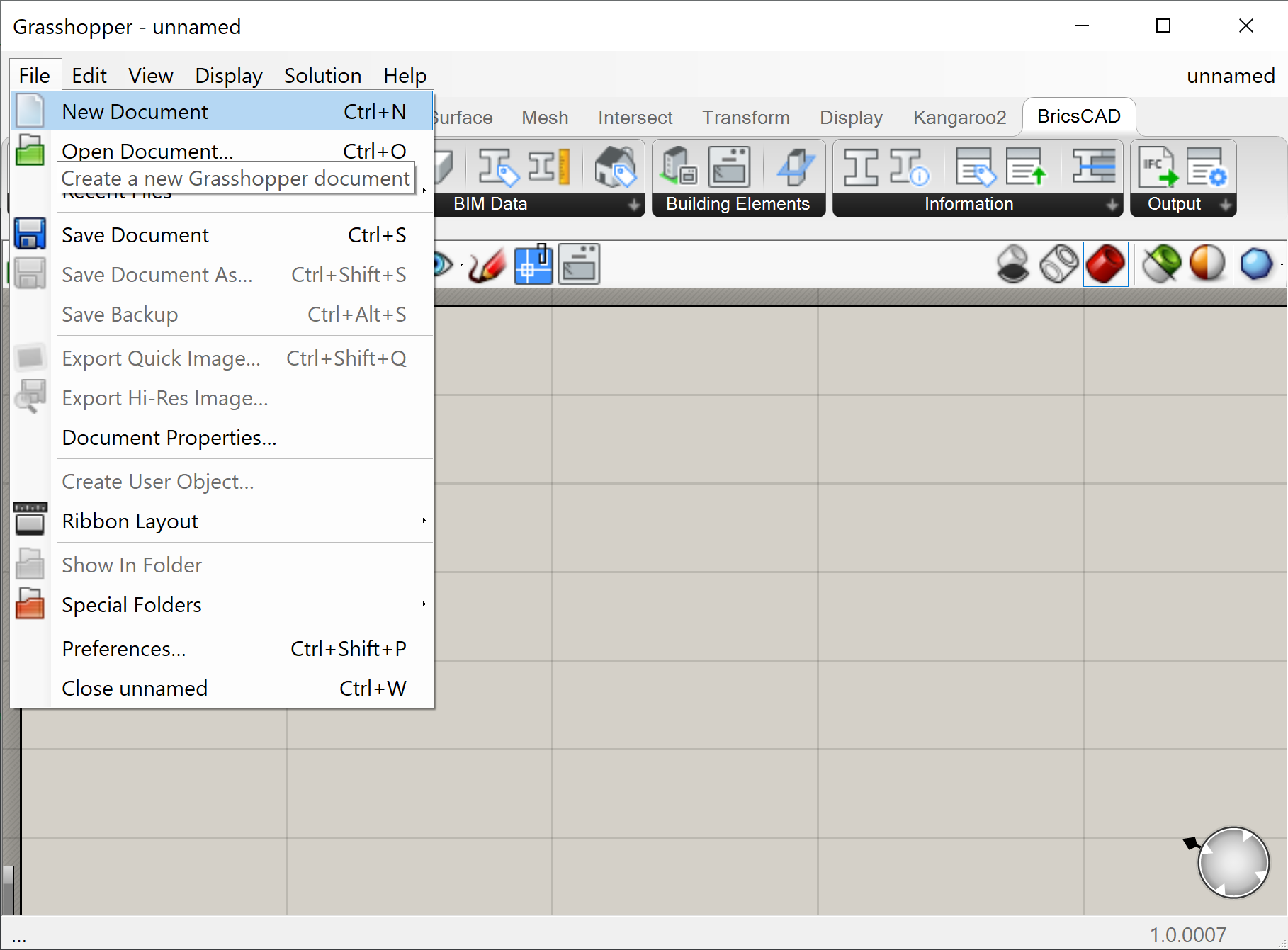
- In the File tab of Grasshopper, choose New document to open a new and empty Grasshopper script.
- Choose Open document... to open an existing Grasshopper script. You can use any script you made with Grasshopper in the past and open it in BricsCAD, as long as the input geometry from another program has been internalized. (To internalize data right-click the input geometry component and hit Internalise data.)
- The geometry you created with the script should now pop-up in your BricsCAD model space, displayed in red. Make sure you don't close the Grasshopper window, otherwise the preview geometry will disappear, as the Grasshopper document is closed.
- If your Grasshopper script is open and you still don't see the preview geometry, it probably means your Grasshopper file is linked to the wrong BricsCAD document. To link it to the correct one, see To link a Grasshopper file with a BricsCAD file.
To link a Grasshopper file with a BricsCAD file
By default, the BricsCAD file that the Grasshopper document will link to the one that was active when you launched Grasshopper from BricsCAD. If you want to link it to another BricsCAD file, you need to:
- Make the target BricsCAD drawing the current drawing (i.e. the one you see in the model space window of your current session).
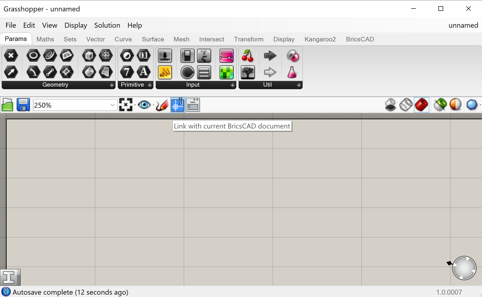
- Link the Grasshopper script to this open drawing. You do that by clicking the Link icon
 in the bar just above the Grasshopper canvas that contains the script that you are trying to link.
To launch a sample file
- Open up a sample .dwg file by opening a .dwg from the Program Files\Bricsys\Grasshopper-BricsCAD Connection folder.
- You will get a warning that the file is read-only. This happens because the document is located in a secured folder. Click Yes to open as read-only.
Optional: If you don't want this warning, or if you want to edit the file, copy-paste the sample files into one of your own folders and open them from there instead.
- From inside Grasshopper, choose . Go to the Program Files\Bricsys\Grasshopper-BricsCAD Connection folder again.
- Choose the .ghx-file with the same name as the .dwg file.
- The sample file now opens and you should see a red preview of the geometry in your BricsCAD model space.
Make sure you don't close the Grasshopper window, otherwise the preview geometry will disappear, as the Grasshopper document is closed. If your Grasshopper script is open and you still don't see the preview geometry, it probably means your Grasshopper file is linked to the wrong BricsCAD document. To link it to the correct one, see To link a Grasshopper file with a BricsCAD file.
- You can play around with the input sliders in the Grasshopper script.
- If you are happy with your model and would like to convert the preview geometry into real BricsCAD geometry, you can 'bake' the geometry into BricsCAD. You do that by selecting all the Bake Building Element components (Shift-clicking them all) and pressing the Bake button
 .
. - A pop-up window appears, just click OK to accept.
- The geometry is now converted into real BricsCAD geometry, even with BIM data attached to it.
- You won't be able to save your changes to your files, as they were read-only. So, discard your changes or save the files as new ones in a different location.
Customizing the Rhino/Grasshopper connection
The code for the Rhino/Grasshopper Connection is 100% open-source and is available at here. This allows you to fully customize your Connector by coding to your heart's content (assuming, of course, that you know how to code).
Uninstall the Rhino/Grasshopper connection
- Launch Add or Remove Programs in Windows.
- Search for Grasshopper-BricsCAD connection.
- Hit Uninstall.
How to draw a box in Rhino and bake into BricsCAD via Grasshopper
- Open a new BricsCAD file.
- Save the file.
- In BricsCAD, click on .
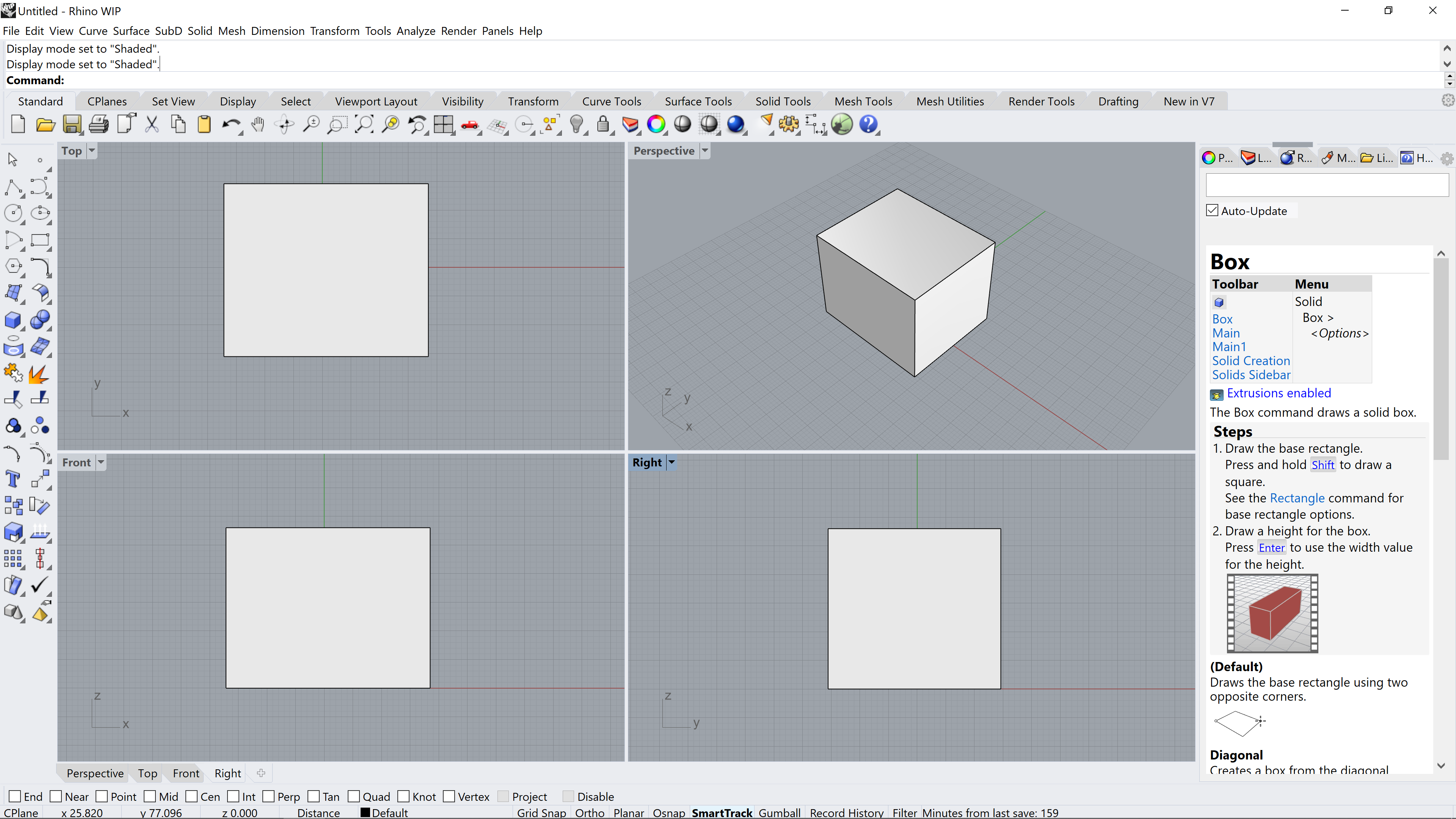
- Draw a Rhino box by typing BOX in the Rhino Command line. (This works in the same way as the BricsCAD BOX command).
- Click for the first corner of the base.
- Click for the other corner of the base.
- Click to define the height of the box.
- To open a new Grasshopper script, inside the Grasshopper environment, click on then click on .
- Save the file.
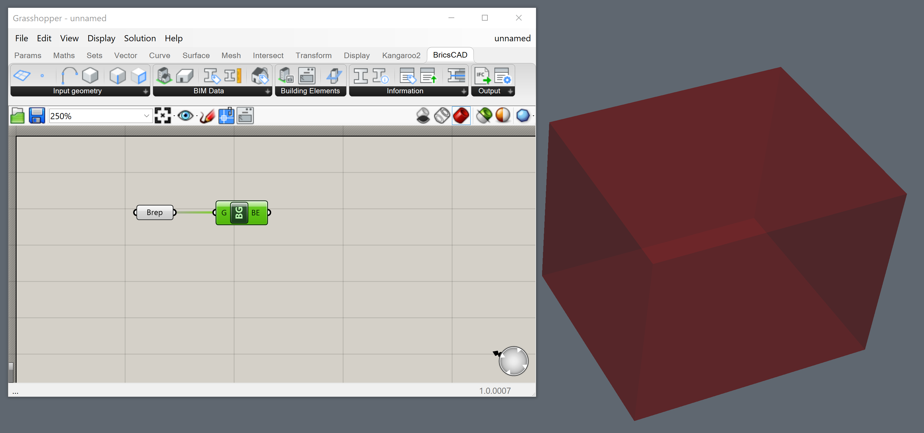
- Drag and drop the onto the Grasshopper canvas.
- Right-click on the component and select Set one Brep.

- Go to the Rhino canvas and select your cube.
- The Brep component will change color from orange to grey. If you close the Rhino window and return to the Grasshopper window, a preview of the cube will display in the BricsCAD model space.
- Drag and drop the onto the Grasshopper canvas.
- To link the two components, click and drag from the Brep component's right dot to the BricsCAD Bake component's left dot.
- Right-click onto the Bake Geometry component and choose Bake into BricsCAD.
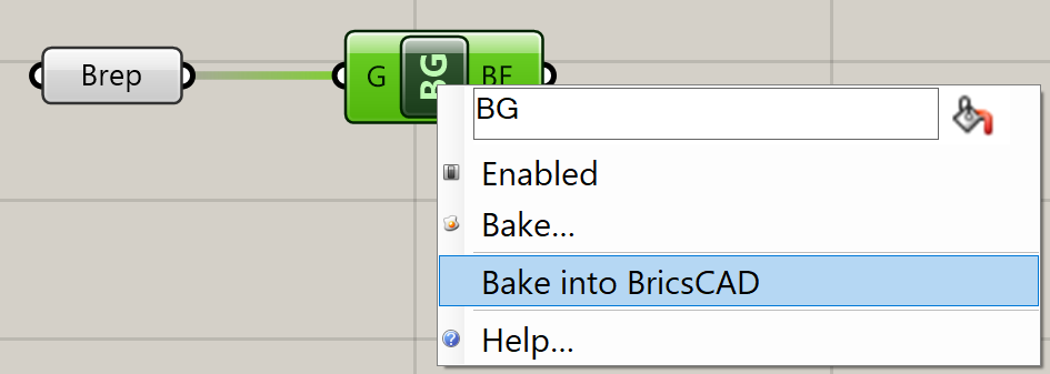
The following dialog displays. Here you can choose the destination Layer, Material and Color: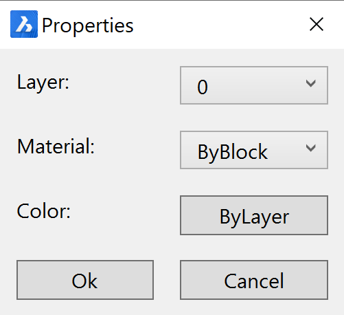
- Click OK. The box is baked as a solid into BricsCAD.
How to draw a box in Grasshopper from a BricsCAD rectangle
- To open a new Grasshopper script, click on and clicking on inside the Grasshopper environment. Save the file.
- Open a new BricsCAD file in a meter template and save it.
- To link the new script to the open .dwg file hit the Link button in the Canvas Toolbar.
- Go to the BricsCAD model space and draw a rectangle.Note: Use a polyline to create irregular geometry.
- Drag and drop the onto the Grasshopper canvas.
- Right-click onto the Curve component and choose Set One BricsCAD Curve.
- Go to the BricsCAD model space and select the rectangle.Note: Save time with the Quad: select the curve in BricsCAD and then select ToGrasshopper under the Grasshopper tab of the Quad. A Grasshopper component appears in the upper left corner of your Grasshopper canvas.
- Link the Curve component to a .
- Link this to a .
- In the Direction input of the Extrude component link a with . Set this to the height of your box, 17 for example.Note: You can edit the range and preciseness of the slider by right-clicking the component and selecting Edit.... A dialog box pops up where you can set the digits and min and max value of the slider.
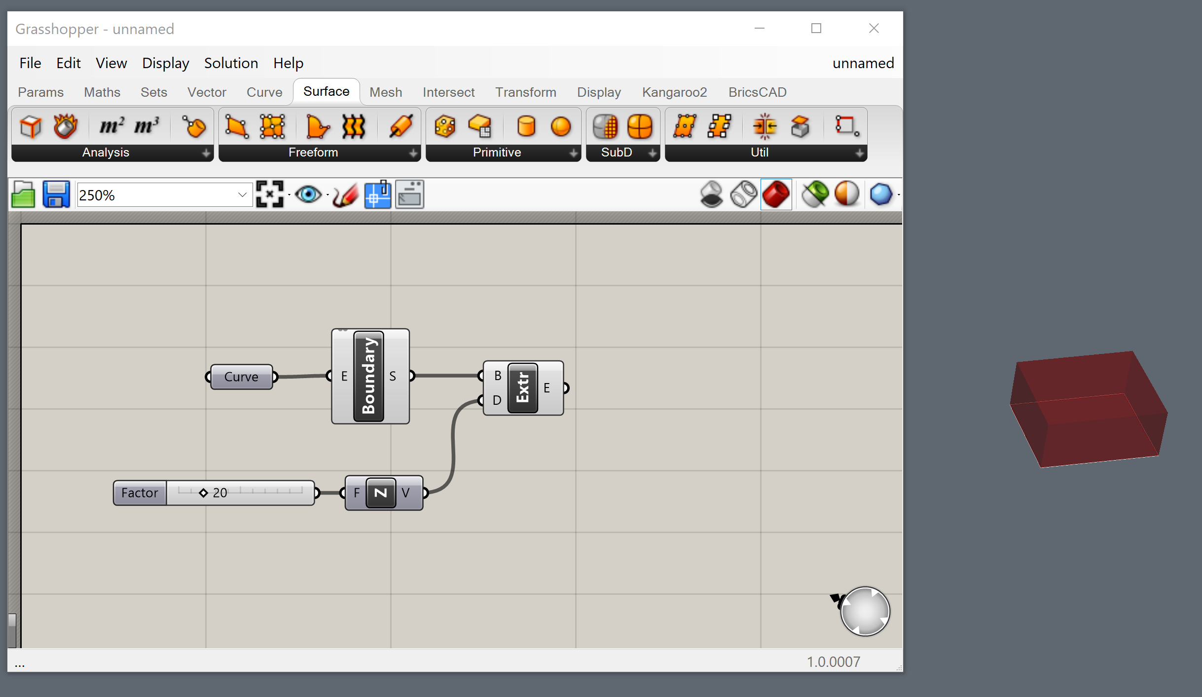
- You now have drawn a box in Grasshopper, using BricsCAD geometry as an input.
How to split up a box into different floors using Grasshopper
- Add the Start_1.ghx-code to your previous Grasshopper script.
- You do that by downloading the zip file at the bottom of this page and extracting its content.
- Then open the Start_1.ghx file by going to in your Grasshopper window.
- You can now select all of the Grasshopper code by hitting Ctrl+A on the keyboard and copy it using Ctrl+C.
- Then switch back to the document you were working on in the previous procedure by going to the upper right corner of the Grasshopper window and clicking on the title of the current document (Start_1).
- You then get a drop-down of all the active Grasshopper scripts, so open the one you saved in How to draw a box in Grasshopper from a BricsCAD rectangle.
- Now click on the canvas and hit Ctrl+V to paste the Start_1.ghx-code.
- Right-click to rename the number slider from the previous procedure to Height building.
- Link this number slider to input A from the Division component in the Compute amount of stories group and to input A from the Subtraction component in the Get last wall height group.
- Link your extrusion to the Shape input of the Contour component.
- Do some cleaning up of the file:
- Drag the green Input group to the front of your canvas.
- Add the Height building slider to the group by selecting the component and then right-clicking on the group and choosing Add to group.
- Put off the preview for your Boundary and Extrusion components: select the components (Shift-click them) and right-click on an empty space of your canvas and choose Preview Off.
- (Optional) For intermediate files that already have these changes, use Intermediate_1.ghx and Intermediate_1.dwg. (Located in the zip file at the bottom of this page.)
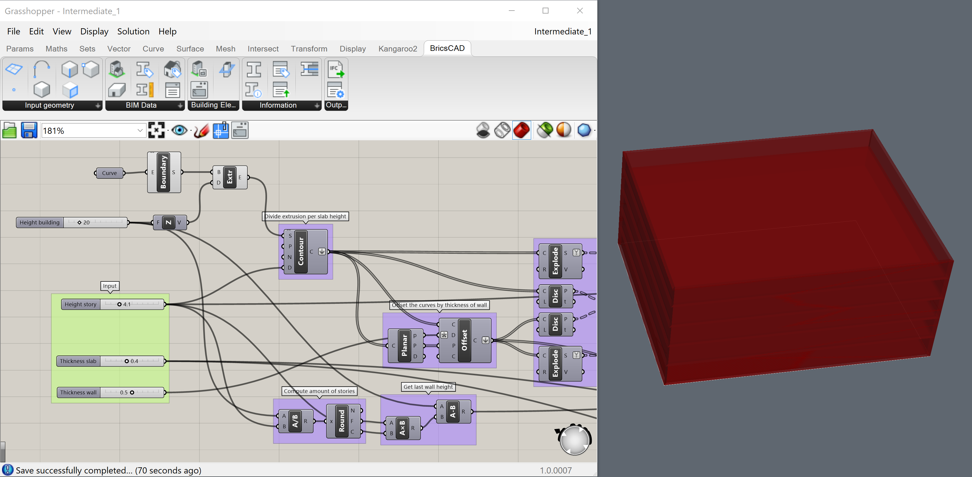
- The script you just made allows you to:
- Divide the extrusion per slab height, using the Contour component.
- Offset the curves by the thickness of the walls.
- Make the bottom surfaces of the walls (the surfaces are split into lower floor walls and roof walls).
- Compute the last wall height.
- Extrude the surfaces into roof, slabs, and walls.
- Adapt the height of the building, the height of the stories, and the thickness of the slabs and walls, by using the sliders in the green Input group.
- Add 3 to the end of your Grasshopper script.
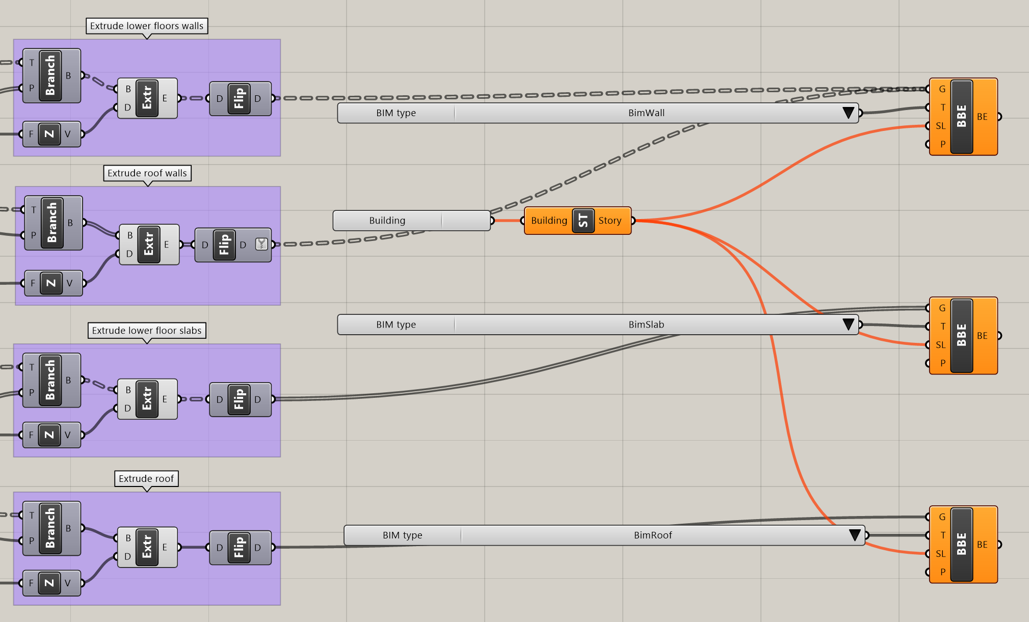
- Attach the extruded elements (the Flip components) to the Geometry input nodes of the Bake Building Element components:
- Connect the extruded lower floor walls and extruded roof walls to one Bake Building Element component. (Hold Shift while connecting multiple nodes to one input node).
- Connect the extruded lower floor slabs to another Bake Building Element component.
- Connect the extruded roof to the remaining Bake Building Element component.
- Add the following components to your canvas from the category: 1 Buildings, 1 Stories, and 3 BIM Types components.
- Attach Buildings to the Building input of the Stories component and attach this to the Spatial Location input of all the Bake Building Element components.
- Attach BIM Types (set respectively to BimWall, BimSlab, and BimRoof in the selection menu) to the Element Type input of the Bake Building Element components of the extruded walls, the slabs, and the roof respectively.
- The following warning will display: Input parameter Building failed to collect data. This is because, when no buildings are defined in the BricsCAD drawing, Grasshopper fails to collect input.
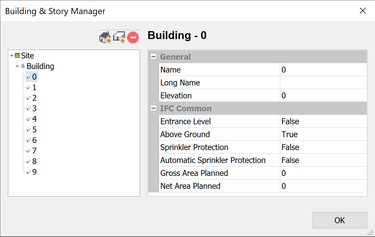
- To make spatial locations, for the component to detect, go to BricsCAD and click on .
- Add a building and a few stories (more stories than you want to divide your building into).
- Go to Grasshopper and right-click the Buildings component and put it onto Drop-down List instead of Check List.
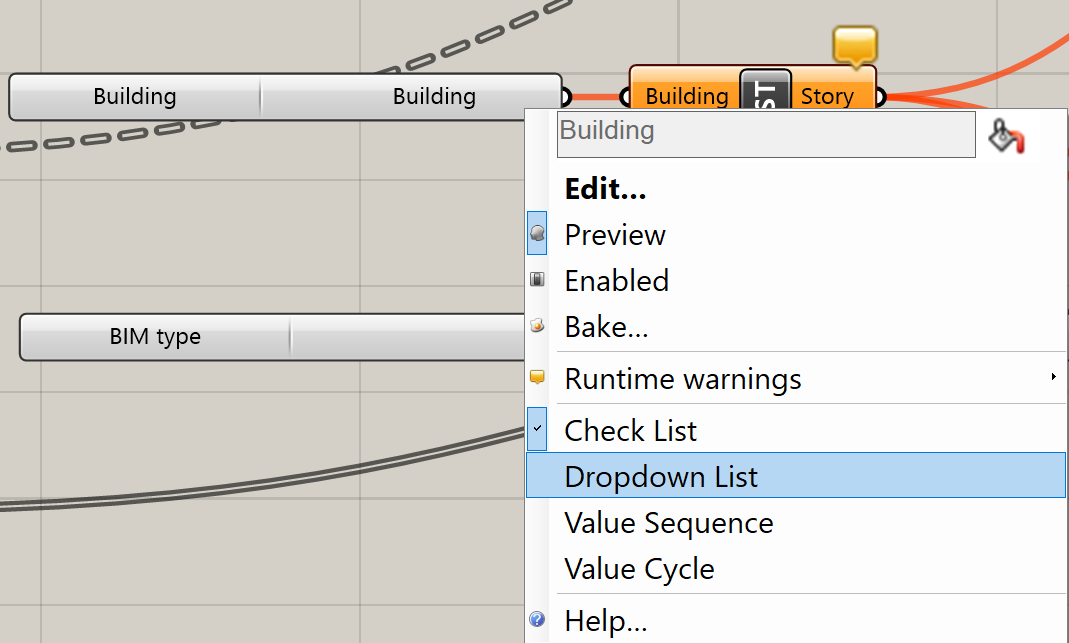
- Select the newly made building in the drop-down list.
- Shift-select all the Bake Building Element components and choose the Bake option from the Canvas Toolbar. Click OK to accept the Layer, Material, and Color.
- The drawing will now have different floors.Note: Check the properties to see that the geometry is correctly classified as Wall, Slab or Roof. These elements will also have a spatial location assigned to them.
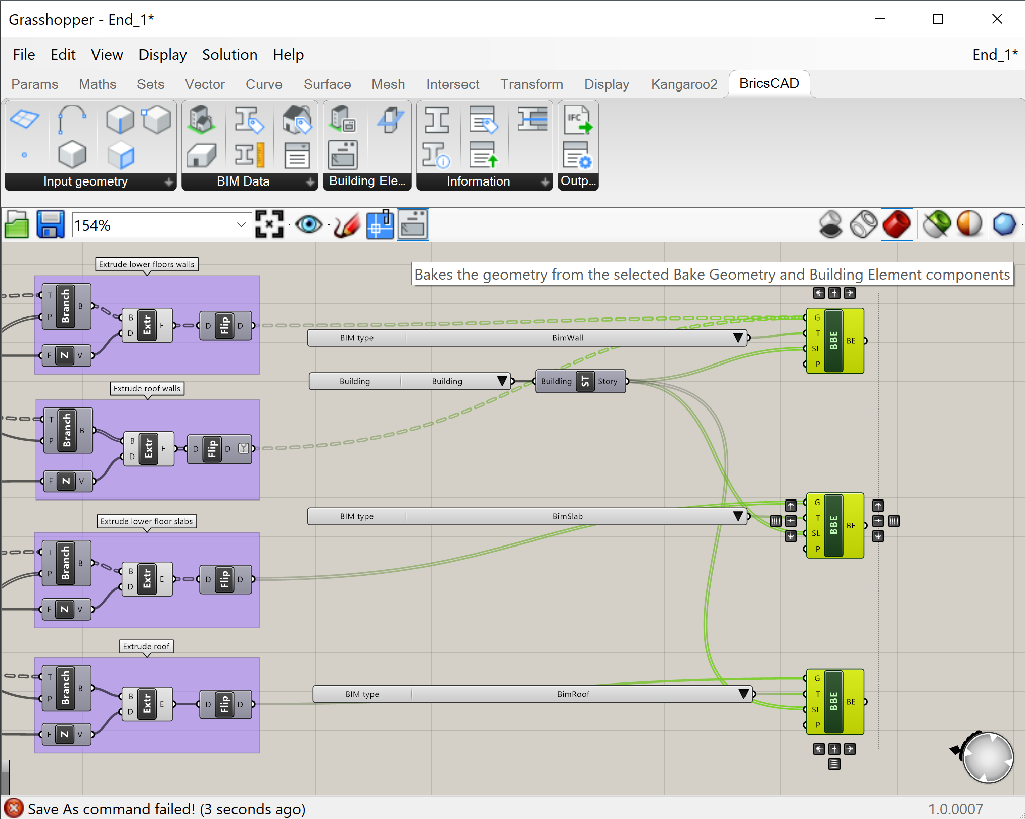
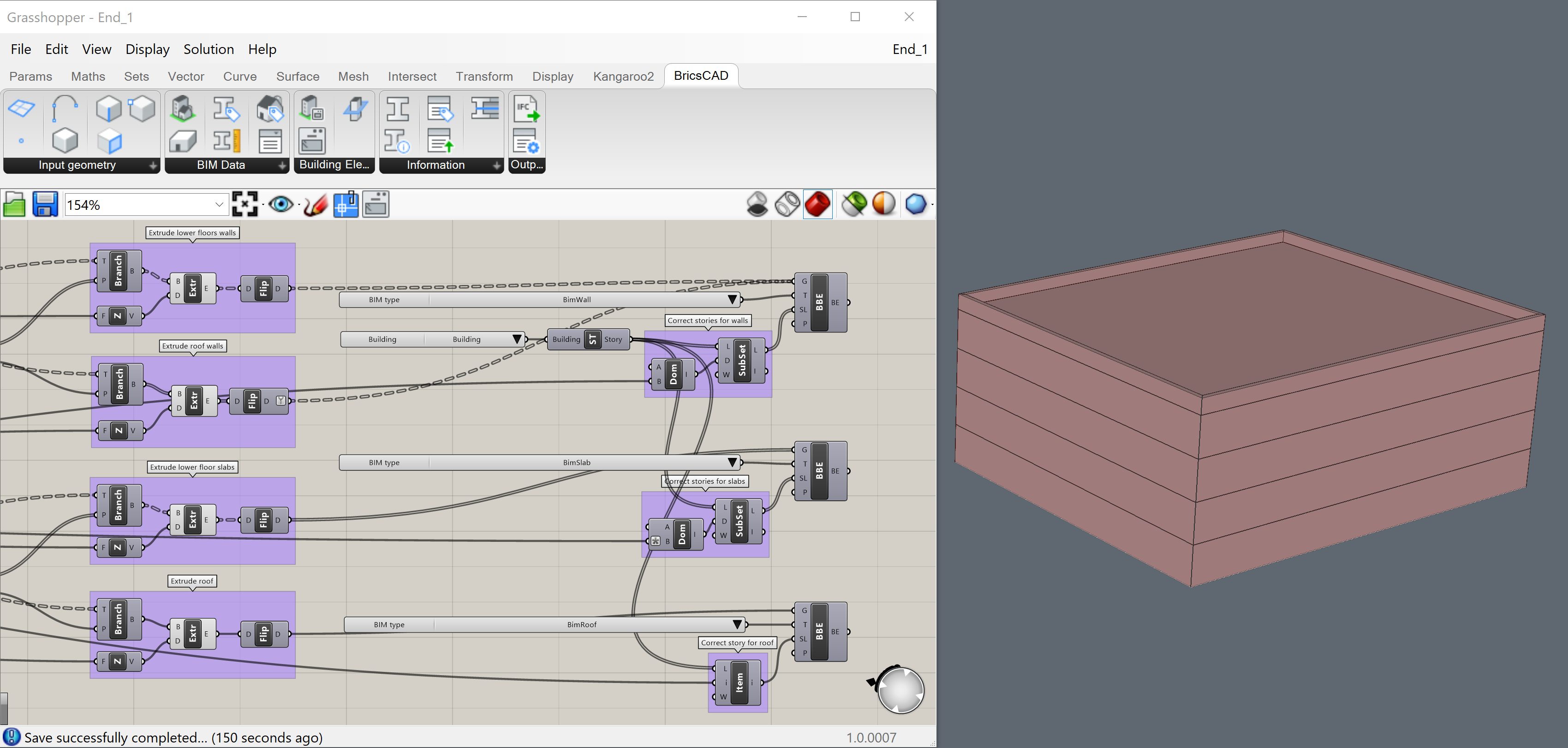
- The last input geometry will be baked onto all remaining stories as there are now more stories than geometry. To correct this, select a correct subset of the stories to assign. Bake the geometry in BricsCAD and the stories will be correct. No duplicate geometry will be baked.
You can see how it's done by opening the End_1.dwg and then opening the Grasshopper file End_1.ghx that is linked to the End_1.dwg.
- You have now successfully created a building.If you want to see the result of the baked building, check the file End_1_Baked.dwg or bake it yourself.
How to add a railing to the top of the building
We will continue with the building made in the previous procedure. So open the End_1.dwg and then open the Grasshopper file End_1.ghx that is linked to the End_1.dwg.
- Add the Start_2.ghx-code to the Grasshopper canvas.
- You do that by downloading the zip file at the bottom of this page and extracting its content.
- Then open the Start_2.ghx file by going to in your Grasshopper window.
- You can now select all of the Grasshopper code by hitting Ctrl+A on the keyboard and copy it using Ctrl+C.
- Then switch back to the document you were working on in the previous procedure by going to the upper right corner of the Grasshopper window and clicking on the title of the current document (Start_2).
- You then get a drop-down of all the active Grasshopper scripts, so open End_1.ghx.
- Now click on the canvas and hit Ctrl+V to paste the Start_2.ghx-code.
- Link the Extrude Roof group's end component to the Brep input of the Deconstruct Brep component of the Select top face of roof group.
- The script does the following:
- The Select top face of roof group will select the top face of the roof.
- The remaining script will take that face and use it to make the baselines for the railing.
- It will then make the axes of the supporting columns and beams.
- It will also calculate half of the height of the beam profile.
- There is still a profile required, however, to complete this step and the following one. We will, therefore, create a profile from step 6 onward.
- With that profile and the axes, the beams and supporting columns are made as extrusions.
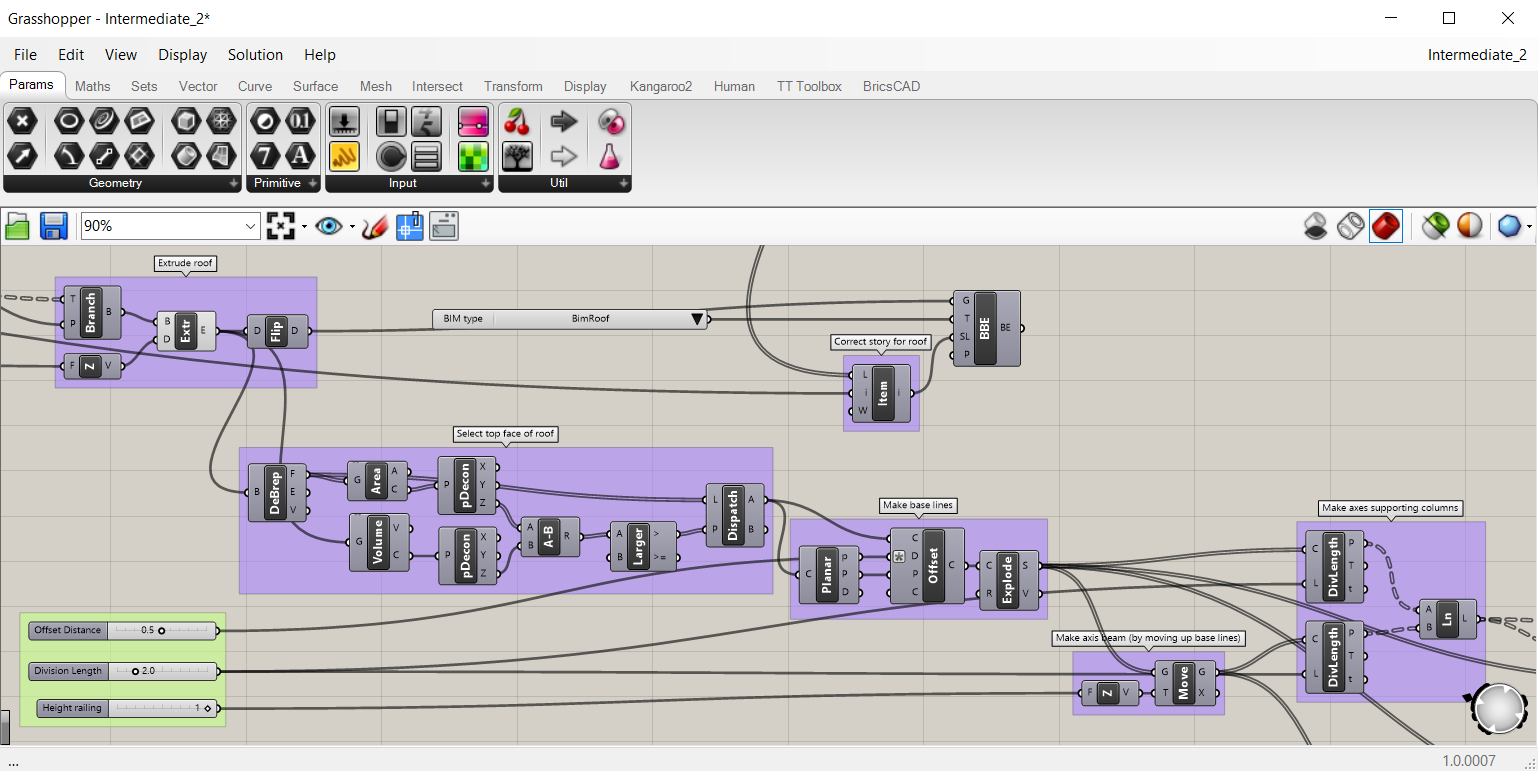
- The intermediate result is found in the Intermediate_2.ghx and Intermediate_2.dwg files. (Located in the zip file at the bottom of this page.)
- (Optional) Skip the Select top face of roof group and replace it with a . Set it to the top face of the roof slab in your BricsCAD baked building. (Do this by right-clicking on the component, click on Set one BricsCAD face and select the face in the BricsCAD drawing). Connect this Face component with a and connect this surface to the correct inputs.
- Go to .
Drag the Profile Names and the Profile Sizes components onto the canvas.
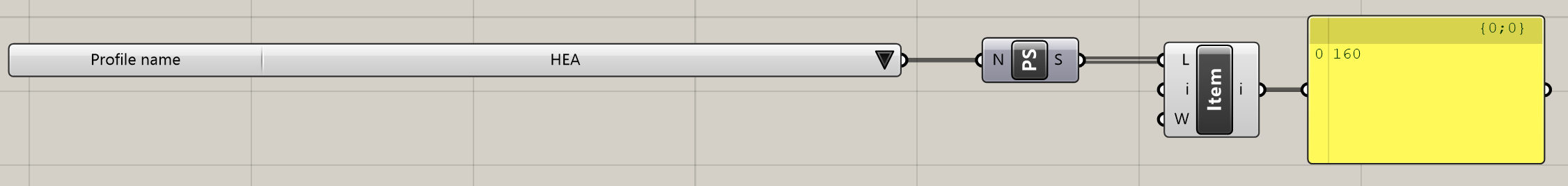
- Select HEA from the drop-down list in Profile Names. This drop-down list displays all the names of the profiles in the Profile Library of BricsCAD.
- Link the component to the input ProfileName of the Profile Sizes component.

- Link the Profile Sizes component to the input node List in a , where i is set to 4 (right-click on the i input and Set integer to 4). This List Item lets you pick one size from the list with all available profile sizes for the Profile Name linked to it.Note: If you link a to the Profile Sizes output, you will see that the index 4 stands for size 160.
Link the Profile Names and List Item components to the , to get an HEA 160 profile as an output.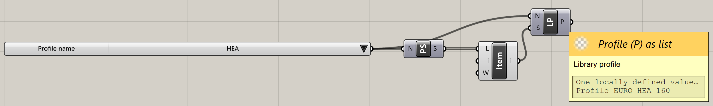
- To get the curves that make up this profile, attach a to the Library Profile. One of the outputs created is the Profile Curves as a tree.
- Attach a to the Profile Curves output node. This is to later extrude the surface as a solid, instead of the lines as a surface.
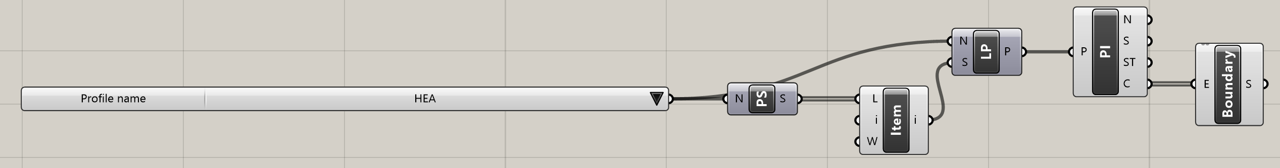
- To group together the components just created, select them (with a selection box) and right-click on Group.
- (Optional) To rename the group, right-click on the purple rectangle. Rename the group in the upper text box, e.g. to Make profile.
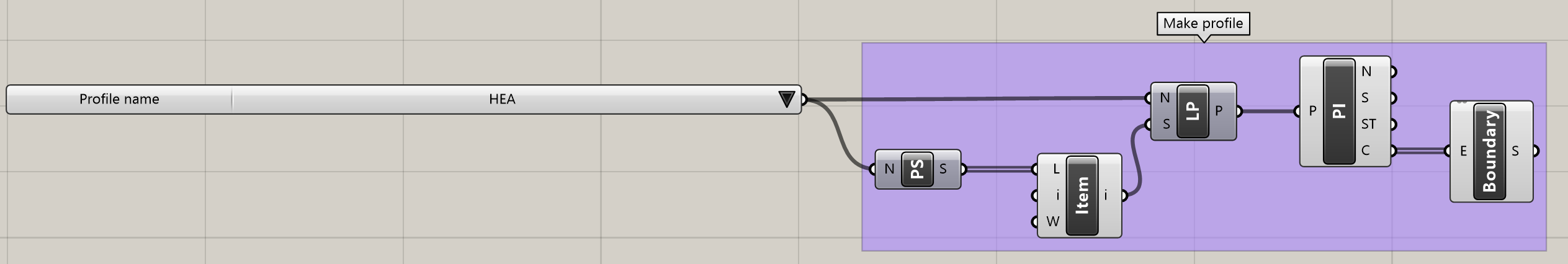
- The Boundary Surfaces component should now be linked to the Content input of the Bounding Box component of the Calculate half of height of beam group. The Boundary Surfaces component should also be linked to the two Profile inputs of the Extrude components in the groups Make supporting columns and Make beams. The extrusions should now show you a railing with HEA 160 beams and columns.
- To bake those beams and columns into BricsCAD attach two to the Grasshopper canvas.
- Do the following:
- Set the Geometry input to the extrusions.
- Set the Element Type input to a , which is set to BimColumn for the column extrusions and to BimBeam for the beam extrusions.
- Set the Spatial Location input to the same as the roof.
- Set the Profiles input to the Library Profiles component from the Make profile group.
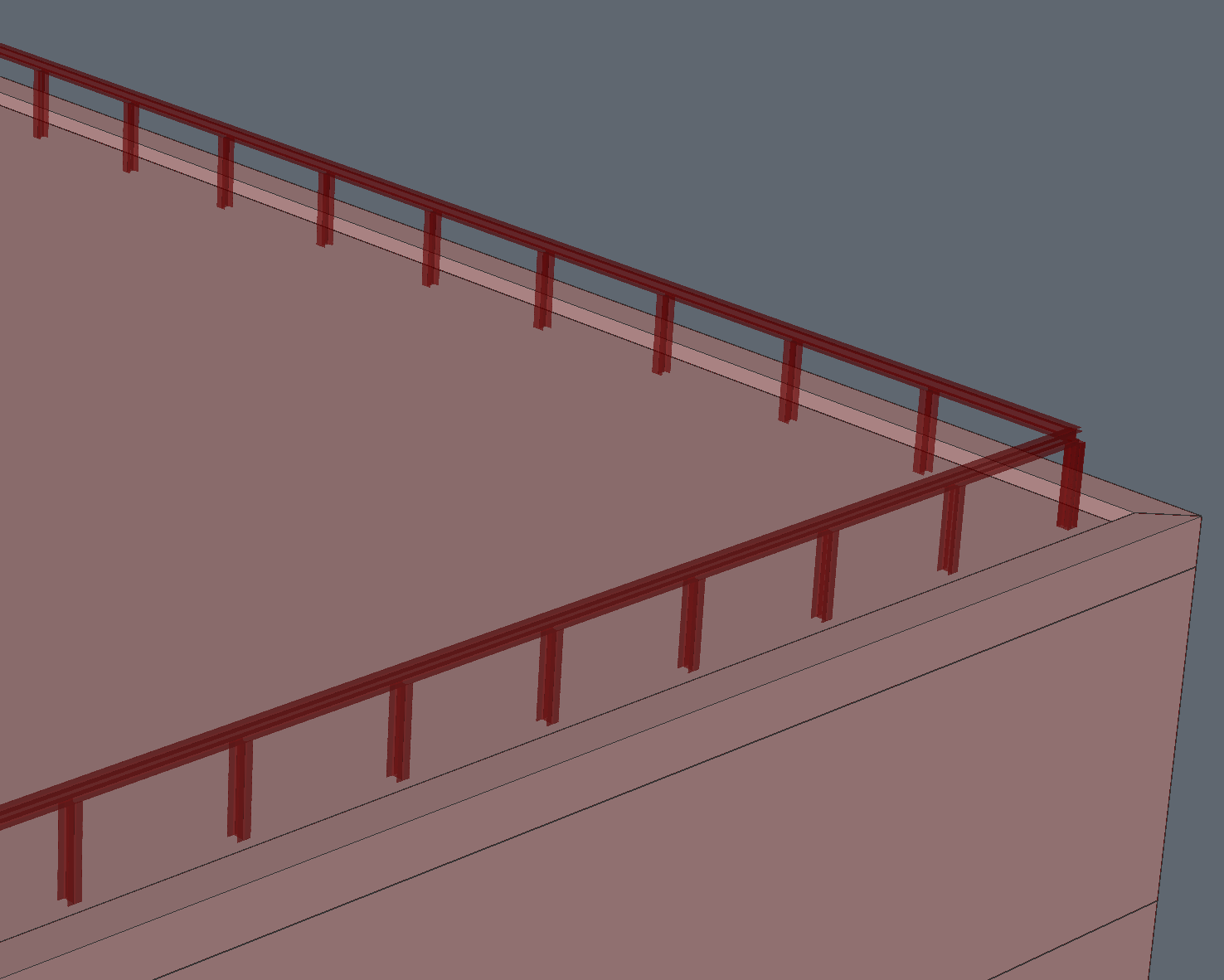
- You now successfully created a railing on top of your building. (The full script to do this is in the End_2.ghx file at the bottom of this page, which is linked to the End_2.dwg.)
- Bake into BricsCAD. The profiles are now set to the one in the Grasshopper script. You can still modify the connections of the beams in the corners by using L-Connect in BricsCAD. (To see the finished building with the railing on top of it, check out the End_2_baked.dwg file at the bottom of this page.)
Procedure: add information to a baked model
We will continue with the building made in the previous procedure. So, open the End_2.dwg and then open the Grasshopper file End_2.ghx that is linked to the End_2.dwg.
- Add the Start_3.ghx code to the canvas.
- You do that by downloading the zip file at the bottom of this page and extracting its content.
- Then open the Start_3.ghx file by going to in your Grasshopper window.
- You can now select all of the Grasshopper code by hitting Ctrl+A on the keyboard and copy it using Ctrl+C.
- Then switch back to the document you were working on in the previous procedure by going to the upper right corner of the Grasshopper window and clicking on the title of the current document (Start_3).
- You then get a drop-down of all the active Grasshopper scripts, so open End_2.ghx.
- Now click on the canvas and hit Ctrl+V to paste the Start_3.ghx-code.
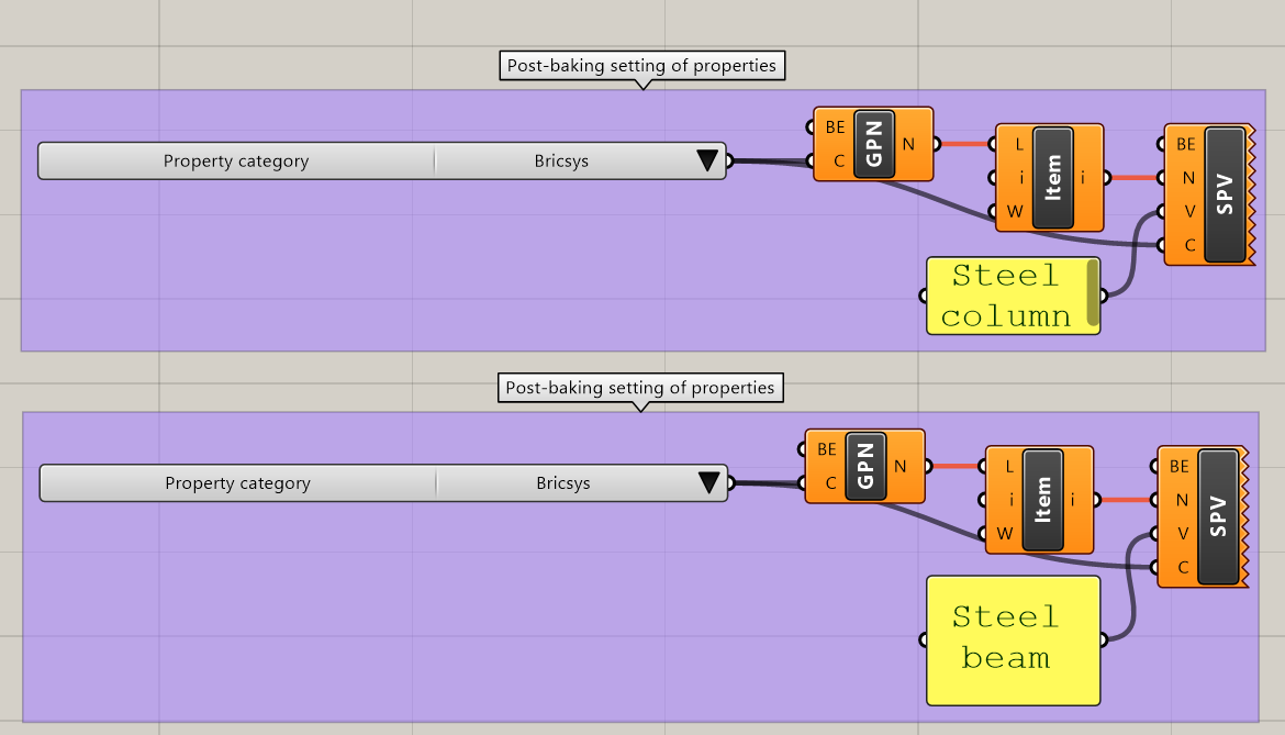
- This code has some post-baking settings of classified and baked beams and columns:
- The script uses the Get Properties Names component to display the BIM properties in the Property category Bricsys.
- In those properties, it selects item 1 for the columns and item 0 for the beams, ColumnType and BeamType respectively.
- To conclude, it sets the properties to the value specified in the Panel components, using the Set Property Value components.
- To make the script work, bake the two Bake Building Element components that make up the railing.
- Now link the Building Element output of the Bake Building Element components to the respective Building Element input of the Get Properties Names components.
- Also, link the Building Element output of the Bake Building Element components to the respective Building Element input of the Set Property Value components.
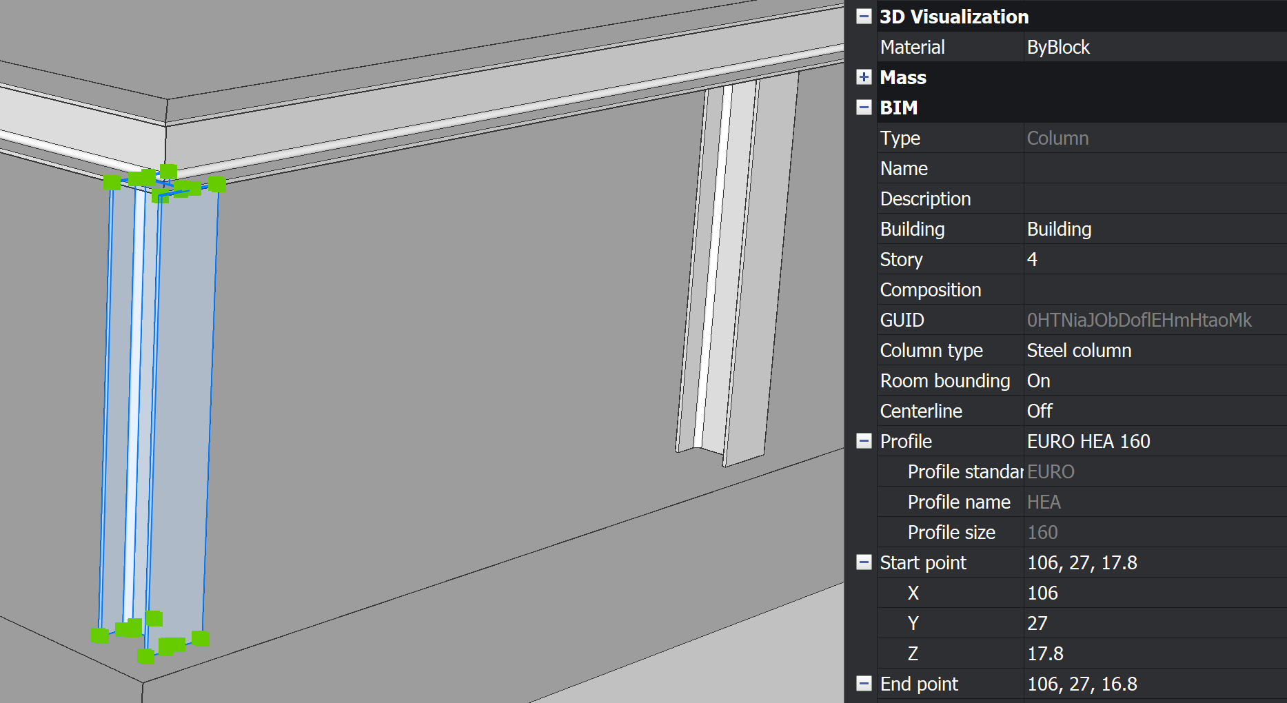
- If you now select a column in BricsCAD and open its Properties, the ColumnType will be set to Steel column. When you change the value of the Panel component, the Properties in BricsCAD change in real-time.
- The resulting script: 'End_3.ghx' can be found in the zip file, located at the bottom of this page. It works with the 'End_3.dwg' file in which nothing is yet baked. Bake all the Building Elements, to get the post-baking settings.
The BricsCAD toolset in Grasshopper
| Icon | Name | Description |
|---|---|---|
 |
Plane | Represents a plane in BricsCAD. |
 |
Point | Represents a point in BricsCAD. |
 |
Curve | Represents a BricsCAD curve. |
 |
Entity | Represents a BricsCAD entity. |
 |
Edge | Represents a BricsCAD edge. |
 |
Face | Represents a BricsCAD face. |
 |
Vertex | Represents a BricsCAD vertex. |
 |
Buildings | Provides a name picker for all the buildings present in Spatial Locations in BricsCAD. |
 |
Stories | Returns all the stories attached to the input building. |
 |
Profile Names | Provides a name picker for all the profiles present in Profiles in BricsCAD. |
 |
Profile Sizes | Returns all the sizes attached to the input profile. |
 |
BIM Types | Provides a type picker for all the BIM Types available in BricsCAD. |
 |
Property Categories | Provides a category picker for all the property categories available in BricsCAD. |
|
|
Bake Geometry | Bake the Grasshopper geometry into the current BricsCAD drawing, while disregarding the BIM data attached to it. The output of Bake Geometry is a reference to the baked building element without BIM data. |
 |
Bake Building Element | Bake the Grasshopper geometry into the current BricsCAD drawing, while adding BIM data to it. The output of Bake Building Element is a reference to the baked building element with BIM data. |
 |
Elements on Spatial Location | By default, returns all the building elements present in BricsCAD. When using input parameters, returns the building elements filtered by element type and/or spatial location. |
 |
Library Profile | Returns a profile from the library, according to the given name and size. |
 |
Profile Info | Returns the information (name, size, standard and curves) of the specified profile. |
 |
Property Names | Returns the property names, attached to a building element, in the specified property category. |
 |
Property Value | Returns the property value, attached to a building element, for the specified property name and category. |
 |
Linear Solid Info | Returns information (axis, extrusion path and profile curves) about a linear solid present in the BricsCAD drawing. |
 |
Set Property | Sets the property value of the building element according to the specified name, category and value. |
 |
IFC Export | Exports the specified building elements to IFC. |
|
|
Link | Links the Grasshopper script to the open BricsCAD .dwg file. |
|
|
Bake | Bakes the geometry from the selected Bake Geometry and Bake Building Element components. |