


Creating a custom window
Creating a custom window
In BricsCAD, you can create any geometry or component from scratch. Once you have your geometry in 3D you can insert and use it in your BIM model. You can make changes or add more details to your window at any time.
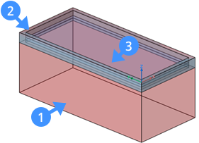
This process is explained in 4 parts to make the steps of creating a 3D window geometry straightforward.
-
Create the file
-
Create the subtractor solid (1)
-
Create the window frame (2)
-
Create the (Glass) panes (3)
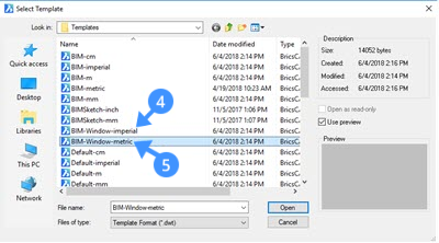
- Click New in the File menu.
- Select one of the pre-defined templates to create a simple window specifying the unit system of your drawing.Note: The pre-defined templates contain the layers needed to create the geometry of the window or door. These .dwt file format templates are BIM-Window-imperial (4) and BIM-Window-metric (5) which assure the required layers and properties are displayed in your drawing.
- Set the BIM_Subtract layer current (6) either using the drawing explorer or layer field in the Properties panel or Layers panel on the right-hand side.

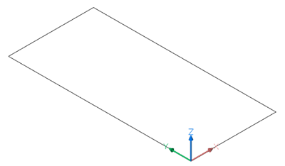
- Create a closed polyline (e.g. a rectangle) that represents the form of the opening for the insert.
- Save the file in any location. The library of predefined windows and doors is located in the support folder.
By default this is: C:\Users<user_name>\AppData\Roaming\Bricsys\BricsCAD\V19x64\en_US\Support\Bim\Components\Windows This path can also easily be found by typing SUPPORTFOLDER in the Command line.
Step 2: Creating the subtractor solid
- Use the outline of the solid which you have previously created (e.g. a rectangle). The outline lies in the first quadrant of the XY plane of the World Coordinate System (WCS).
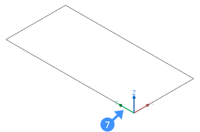
The lower left corner of the rectangle lies at the origin (0,0,0) of the WCS (7).
- Select the Extrude tool and move the cursor downward (8) to extrude your solid outline in the negative Z direction.
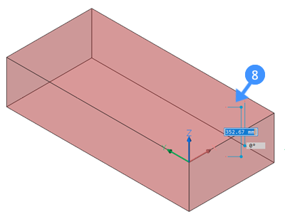
- Do one of the following to finish the subtractor solid creation.
- Click a point.
- Type a value in the dynamic dimension fields, then press Enter.
Step 3: Creating the fixed frame
The outline of the fixed frame coincides or is parallel (in case of a rebate) with the outline of the subtractor solid.
- Set the Window_Frame layer current.
- Highlight the top face of the subtractor solid.
- Next, extrude the top face of the subtractor solid in the negative Z direction (9) using the Extrude tool ‘Create’ (10) option by pressing the CTRL key once.
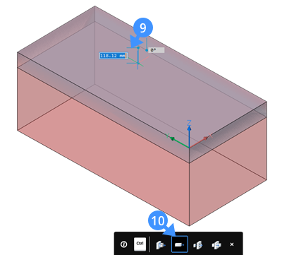
- Type a value in the dynamic dimension field to specify the height of the fixed frame.Note: The height of the extrusion will be the thickness of the fixed frame.
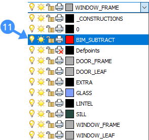
- Turn off the BIM_SUBTRACT layer by clicking the light bulb (11) next to the layer name.
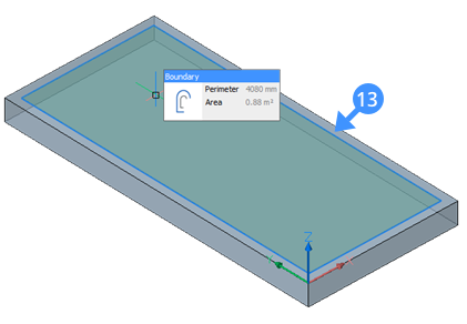
- Use the Offset tool to create a parallel offset of the outline of the fixed frame (12).
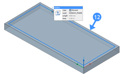
Note: The distance of the offset equals the width of the frame. - Hover over the inside boundary of the parallel offset (13) and select Extrude tool from the Quad.
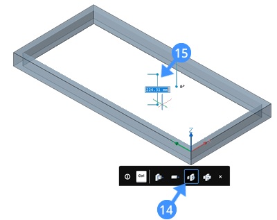
- When the extrude mode is on the Subtract option (14) move your cursor downward (15) to create an opening in the fixed frame.
- Do one of the following to finish the creation of the opening in the fixed frame.
- Click a point.
- Type a value in the dynamic dimension fields, then press Enter.
- Set the Glass layer current.
- Use the DMEXTRUDE command to extrude the inside boundary of the window frame.Note: The height of the extrusion equals the thickness of the glass pane. The following illustration shows the inside boundary of the window frame after using DMExtrude to create a window glass pane.
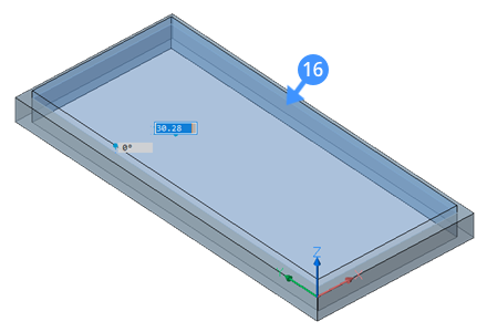
Note that to create a glass pane, the create option should be selected from the Tooltip of DMExtrude.
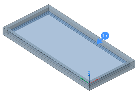
- Move the glass pane solid down in the negative Z-direction if the outside face of the fixed frame does not coincide with the outside face of the solid (wall) the insert will be placed in.The following illustrations show the glass pane solid after moving it (17) down.
- Optionally, before saving the drawing, classify the BIM as a window element.
To do so, follow these steps:
-
Type BIMCLASSIFY in the Command line.
-
Press 'I' for window and press enter to accept it.
-
Next, press 'D' for Drawing and press the Enter key until the command is executed.
The drawing is classified as a window. When you insert this block in your drawing, it will automatically be classified as a window.
-
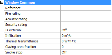
- Optionally, when no selection is active, you see a set of BIM properties on the right-hand side of your screen. Here you can assign information about the thermal transmittance coefficient of the window materials, fire rating according to the national fire safety classification, and so on. The following illustration shows the BIM properties of the window in the properties panel.
- Save the drawing.
Adding 2D entities
Optionally, windows and doors drawings can contain 2D symbols. These 2D symbols will either replace the actual 3D Solid section of the window or door or be added to the 3D Solid section, depending on their layer:
- Symbols on a layer with prefix “BRX_2D_” or “BRX_2D+_” will be added to the section block:
- without being processed by analytical hidden line removal (HLR) when the section plane intersects the components.
- after going through analytical hidden line removal (HLR) procedure when the section plane does not intersect the components.
- Symbols on a layer with prefix “BIM_2D_SECT_“ or “BIM_2D_SECT+_ “ will be added only when the section plane intersects the components. All geometry goes through analytical hidden line removal (HLR) procedure.
- Symbols on a layer with prefix “BIM_2D_BACK_” or “BIM_2D_BACK+_” always will be added and all geometry goes through analytical hidden line removal (HLR) procedure.
- Symbols layers name
- with “+”: both the 2D symbol and the 3D solid section of the component are shown in the section result.
- without the '+' only the 2d content is shown and all solids in the component are ignored for section generation.
Note: BRX_2D is still available only for backwards compatibility.