MEP flow connection points
Commands
BIMLINEARSOLID, BIMFLOWCONNECT
About
When creating flow elements like Flow Terminals and Flow Segments, you can add a 2D symbol and classify it as a Flow Connection Point. A flow connection point contains BIM data where you can predefine the profile you want to use with this flow component. When you select the flow connection point and use the commands BIMLINEARSOLID or BIMFLOWCONNECT, BricsCAD will automatically use a BIM Profile based on the given information.
See the related links for more information about Linear Solids.
See the related links for more information about MEP modeling.
Procedure: creating a flow connection point
In this procedure, you will learn how to create your own HVAC components with flow connection points. As an example, we will create an air heat pump unit.
Creating a flow connection point in the Library panel- Draw a box with the desired dimensions (80x40x80 cm) representing the heat pump.
- Select the box and launch BIMCLASSIFY with the <Other> option or hover over the box and select Classify Manually in the BIM tab of the Quad.
- Classify the box as and click OK.
- Open the Library panel.
- Go to the MEP Flow Connection Points.
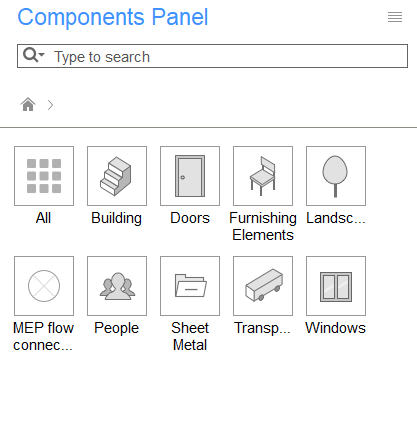
- Place HVAC Outlets Round on the heat pump box.
- Select the Outlet and click the
BIM/Profile property in the
Properties panel.
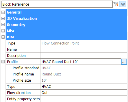
- Click the browse (
 ) button.
The Profiles dialog box displays.
- Set Type and Standard = HVAC.
- Choose the desired profile and click the Select button.
- Go back to the Library panel and click Create Component.
- Choose a name and category and click the OK button.See the Components Panel article for more information about adding a component to the library.
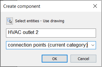
The drawing is now saved as a component and can be used in other drawings.
- Draw a box with the desired dimensions (80x40x80 cm) representing the heat pump.
- Select the box and do one of the following:
- Launch BIMCLASSIFY with the Other option.
- Hover over the box and select Classify Manually in the BIM tab of the Quad.
- Classify the box as and click OK.
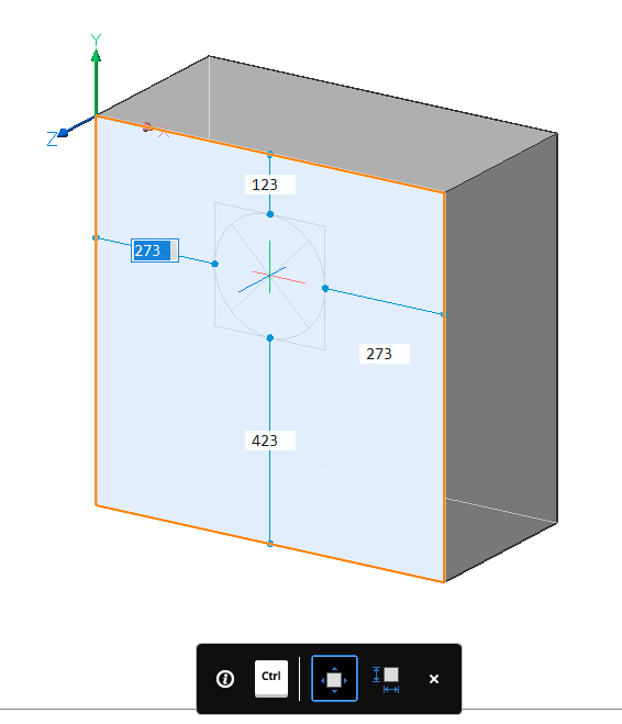
- Draw a circle on the top face of the box.
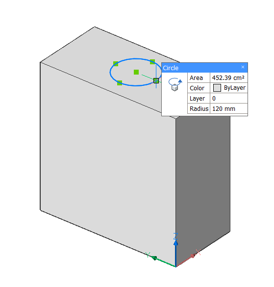
- Select the circle and launch BIMCLASSIFY with the Other option.
- Classify the circle as and click OK.
- Select the circle.
- In the Properties panel, select the
BIM/Profile property and
click the Browse ()
button.
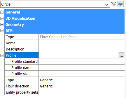
The Profiles dialog displays.
- Select the desired profile and click Select.
- On the Library panel and click Create Component.
- Choose a name and category and click OK.
The drawing is now saved as a component and can be used in other drawings.
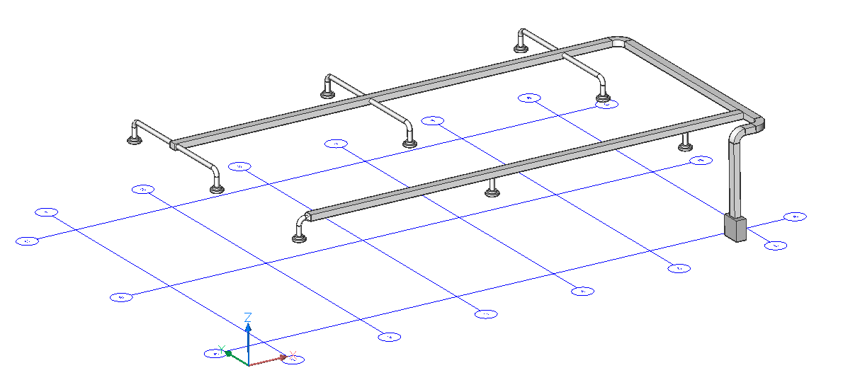
Procedure: Creating an HVAC System
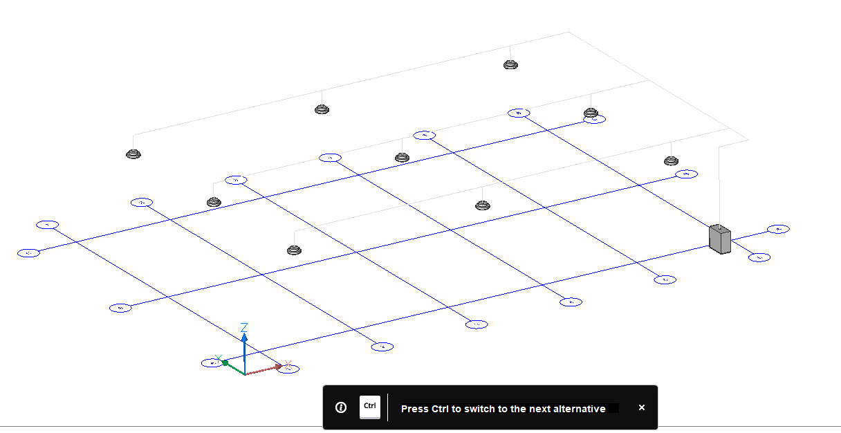
- Let's start from a file with a series of flow terminals and a ventilation unit.
- Select the flow terminals and the ventilation unit.
- Select FlowConnect in the Quad or in the Structural/MEP ribbon tab.
- Press the CTRL-key to switch between the alternative setups and press
Enter.
- Click the Tune option or enter T in the Command line to modify the chosen setup.
- Select Topology in the toolbar or enter T and press Enter.
- Select the check icons to modify the layout of the system.
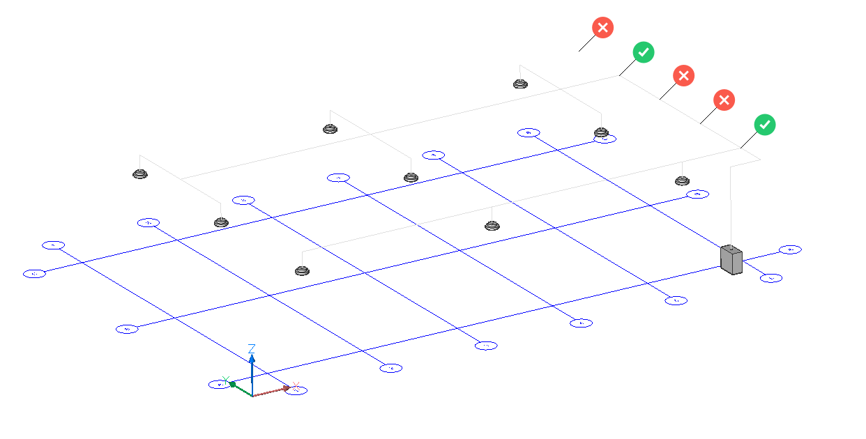
- Press Enter 3 times to exit the command.Note: BricsCAD automatically uses the profiles that were assigned to the ventilation units. This information is stored in the Flow Connection Points.