Modelowanie MEP
Polecenia
BIMZASTOSUJPROFIL, BIMBRYŁALINIOWA, BIMPOŁĄCZENIEPRZEPŁYWU, DYNAM, BIMROZCIĄGNIJ
Informacje o BIMPOŁĄCZENIEPRZEPŁYWU
Możliwe jest również łączenie różnych segmentów za pomocą polecenia BIMPOŁĄCZENIEPRZEPŁYWU.

Aby uzyskać więcej informacji na temat tego polecenia, zapoznaj się z artykułem Dokumentacja poleceń BIMPOŁĄCZENIEPRZEPŁYWU.
Łączenie ze sobą różnych segmentów
Wybierz segmenty, które chcesz połączyć i uruchom polecenie BIMPOŁĄCZENIEPRZEPŁYWU.
Po włączeniu Asystenta klawiszy skrótu(HKA na pasku stanu) na ekranie pojawi się następujący widżet. Naciśnij klawisz CTRL, aby przełączać się między różnymi opcjami.
Zakończ polecenie, naciskając Enter, segmenty są teraz połączone.
Procedura: zmiana położenia segmentów
Przed rozpoczęciem procedury: włącz wybór boków i końców:

Kliknij ikonę na pasku narzędzi Tryby wyboru lub ustaw zmienną systemową DISPLAYSIDESANDENDS na WŁ.
DYNAM
Polecenie DYNAM umożliwia modyfikację segmentu narysowanego profilu bez utraty połączenia z innymi segmentami.

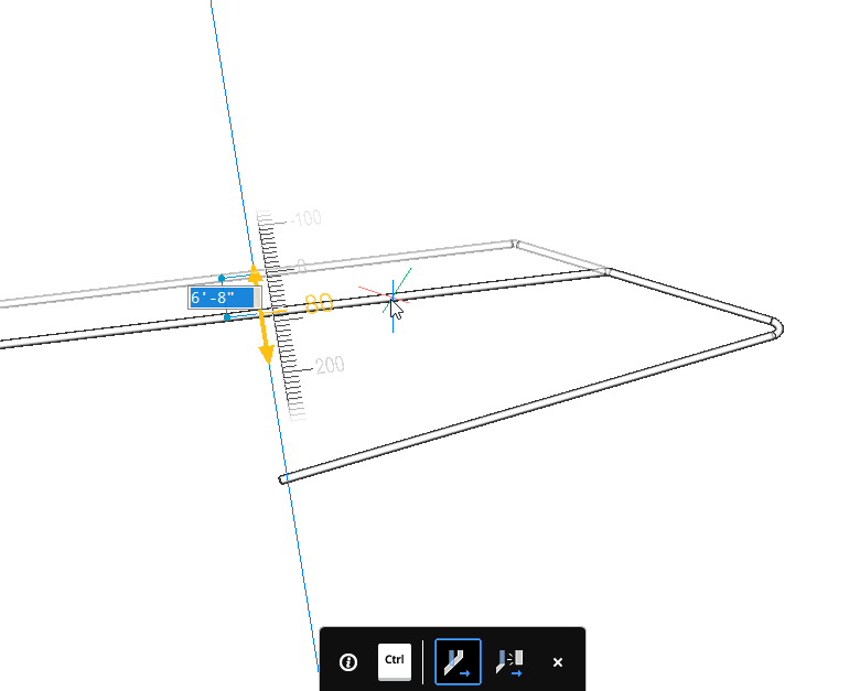
- Najedź kursorem na segment, wybierz powierzchnię prostopadłą do przekroju profilu.
- Uruchom polecenie DYNAM.
- Wybierz nową pozycję segmentu lub użyj pola wymiaru dynamicznego, aby wprowadzić wartość przemieszczenia.Uwaga: Oprogramowanie automatycznie regeneruje połączenie między segmentami.
- Najedź kursorem na segment, wybierz powierzchnię prostopadłą do przekroju profilu.
- Wybierz opcję Manipuluj.
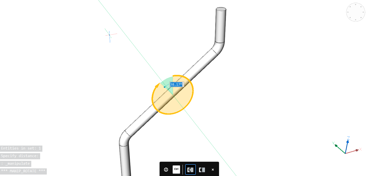
- Wybierz nową pozycję segmentu lub użyj pola wymiaru dynamicznego, aby wprowadzić wartość obrotu.
- Kliknij nową pozycję lub wprowadź kąt obrotu i naciśnij Enter.
Procedura: Używanie narzędzi modelowania MEP do rysowania i łączenia profili
- Otwórz rysunek zawierający model MEP. Możesz pobrać ten plik MEP.zip zawierający rysunki na końcu tego artykułu.
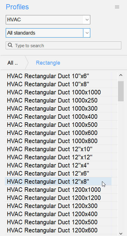
- Otwórz panel BIM Profile po prawej stronie ekranu (patrz Panele dokowane).
Przefiltruj HVAC i wybierz profil Rectangular 12 "x 8", a następnie przeciągnij go do przestrzeni modelu.
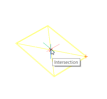
- Umożliwia zdefiniowanie punktu początkowego profilu.
Przyciągaj do geometrycznego środka żółtego prostokąta.
- Włącz funkcję Ortho i zdefiniuj kolejne punkty profili za pomocą pola wymiarów dynamicznych.
Quarter obraca profil, wpisując Q w wierszu poleceń.
Idź w górę 3,5, idź 3,5 w lewo i idź 21 poziomo.
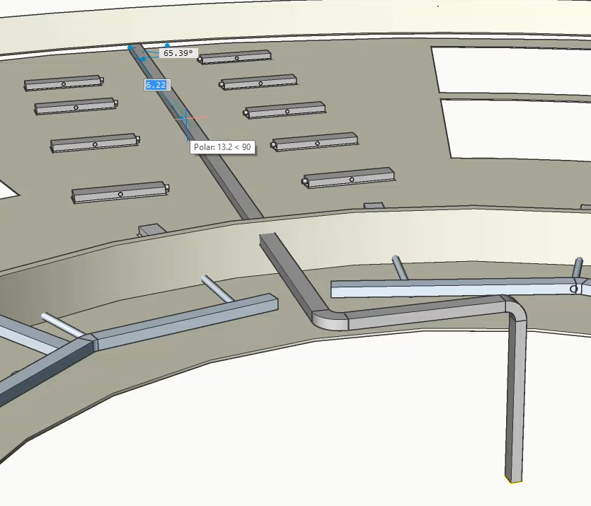
Uwaga: Jeśli wybrałeś profil inny niż HVAC, nie otrzymasz automatycznej klasyfikacji jako Segment Przepływu. Profile można ręcznie sklasyfikować za pomocą polecenia BIMKLASYFIKUJ jako Elementy serwisowe budynku - Segment przepływu. - Połącz pozostałe prostokątne kanały z boku z tym, który właśnie utworzyliśmy.
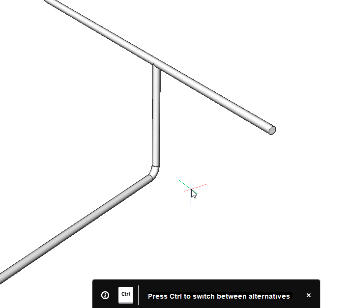
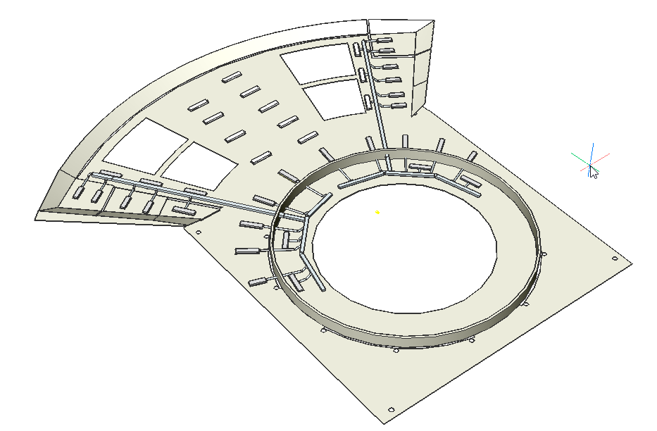
Wybierz kanały razem z kanałem głównym i uruchom polecenie BIMPOŁĄCZENIEPRZEPŁYWU. Twoje połączenie powinno wyglądać jak na poniższym obrazku.
- Utwórz kanał z terminala przepływowego.
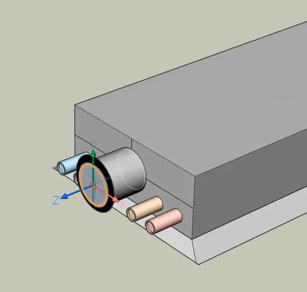
Uruchom polecenie BIMBRYŁALINIOWA i wybierz przyłącze przepływu.
Ten punkt połączenia zawiera informacje o profilu, więc oprogramowanie automatycznie tworzy predefiniowany okrągły kanał. Nadaj kanałowi długość 1.
- Podłącz kanały od terminala przepływowego do prostokątnego kanału głównego.
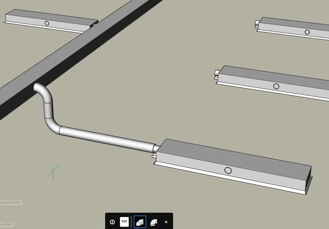
Wybierz kanał główny i kanał z terminala przepływowego i uruchom polecenie BIMPOŁĄCZENIEPRZEPŁYWU.
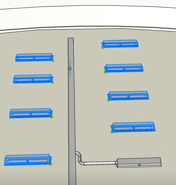
- Podłącz wszystkie pozostałe zaciski przepływu do prostokątnego kanału jednocześnie.
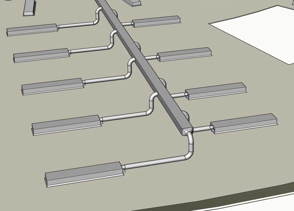
Wybierz pozostałe terminale przepływu i kanał prostokątny i uruchom polecenie BIMPOŁĄCZENIEPRZEPŁYWU.
- BricsCAD wykorzystuje informacje z punktu przyłącza przepływu do określenia typu kanału używanego do połączenia z kanałem głównym.Uwaga: Zacisk przepływu z tyłu jest podłączony do tylnej części prostokątnego kanału.
Procedura: Użycie narzędzi modelowania MEP do zmiany profili
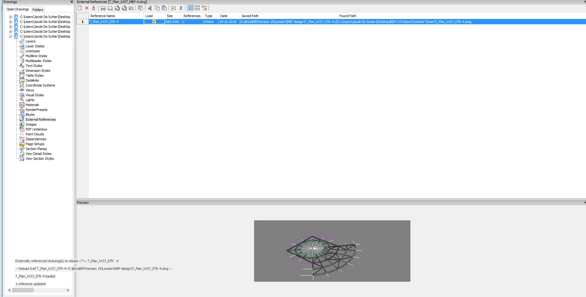
- Wpisz ODN w wierszu polecenia i zaznacz pole obciążenia obok modelu konstrukcyjnego, aby wczytać rysunek konstrukcyjny.
- Użyj polecenia PODZIAŁ i opcji MultiPodział, aby podzielić prostokątny kanał.
Wprowadź wartość 3 w polu wymiarów dynamicznych i naciśnij Enter, aby zakończyć polecenie.
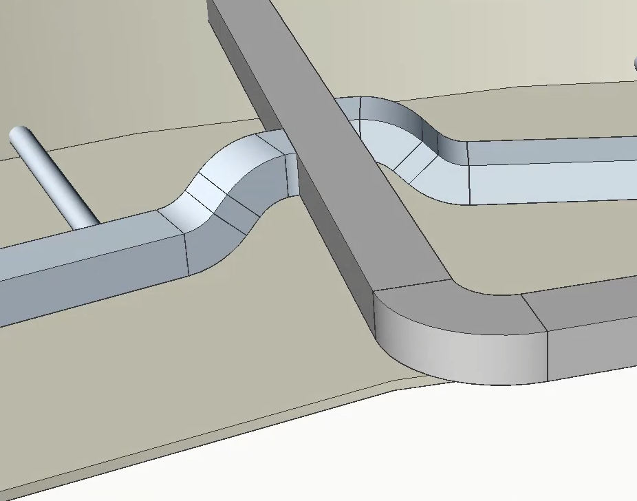
- Zmień położenie prostokątnego kanału, aby nie kolidował z modelem konstrukcyjnym.
Wybierz górną ścianę kanału i uruchom polecenie DYNAM.
Uwaga: BricsCAD zachowuje połączenia z kanałami okrągłymi. Możesz to zmienić, naciskając klawisz CTRL, jeśli chcesz odłączyć kanały.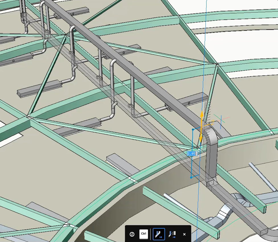
Przesuń kanał w dół o 0,23.
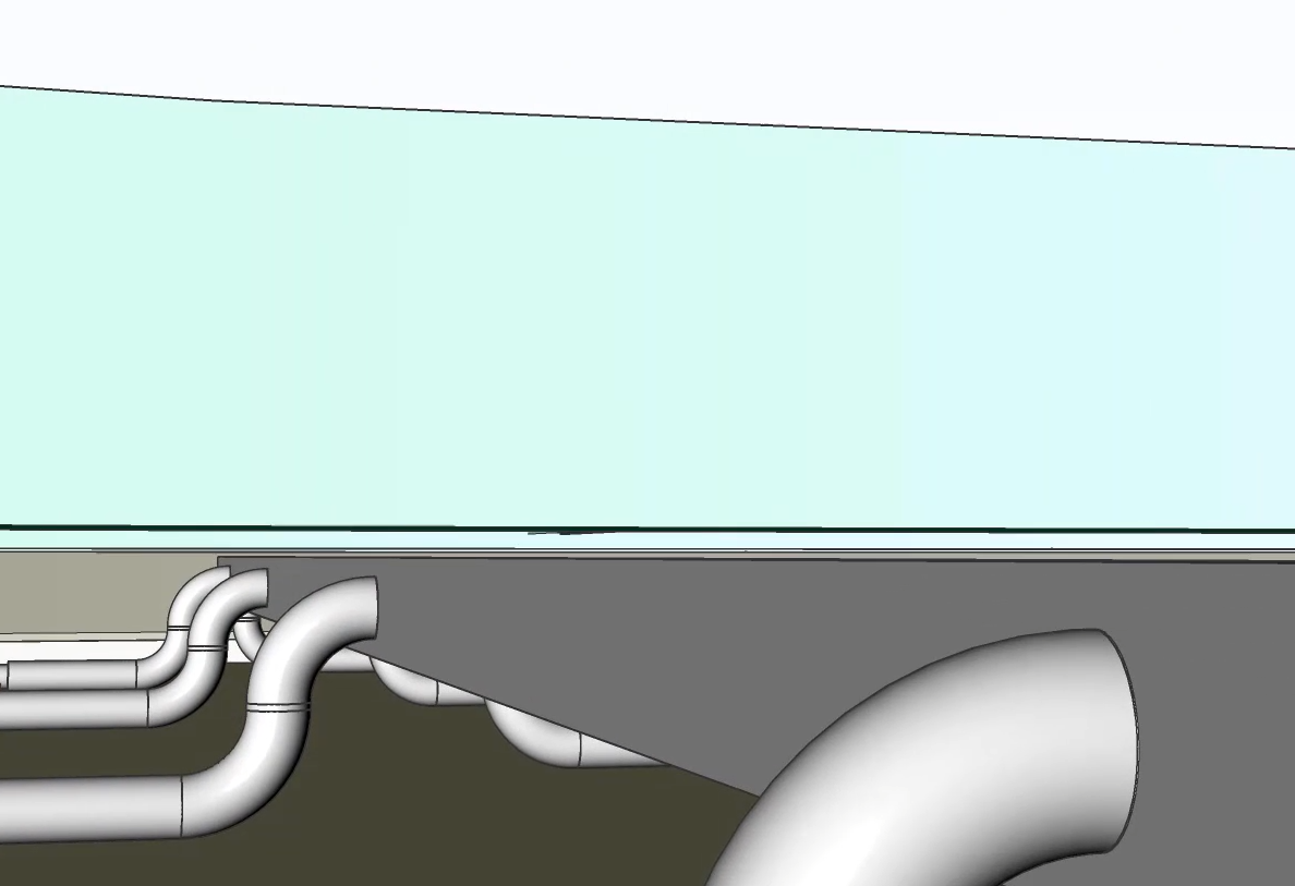
- Model konstrukcyjny nie koliduje już z modelem MEP, natomiast połączenia między kanałami terminali przepływowych a głównym kanałem prostokątnym zostały zachowane.Uwaga: Podczas przesuwania Terminalu Przepływu za pomocą Manipulatora, jego połączenia z Segmentami przepływu pozostają nienaruszone.
Procedura: użycie Bimstretch do modyfikacji segmentów przepływu
- Otwórz nowy rysunek.
- Otwórz panel BIM Profile, klikając go po prawej stronie ekranu.Uwaga: Jeśli ikona panelu BIM Profile nie jest jeszcze widoczna, kliknij prawym przyciskiem myszy wstążkę i wybierz BIM Profile w menu kontekstowym.
- Filtr w standardzie HVAC. Profile te zostaną automatycznie sklasyfikowane jako segmenty przepływu po przeciągnięciu ich do przestrzeni modelu.
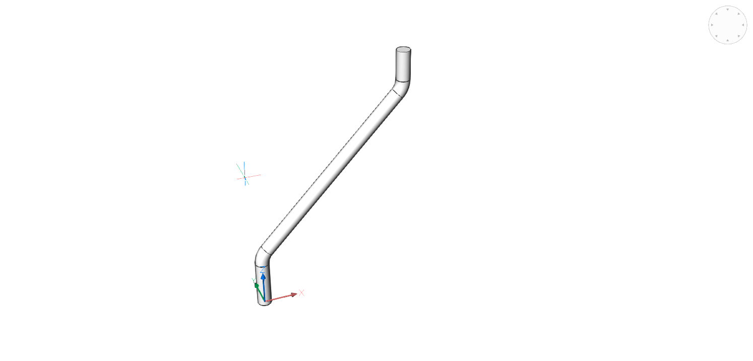
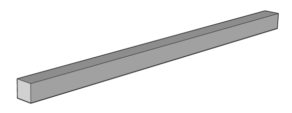
- Wyszukaj profil HVAC Rectangular Duct 10''x10'' w panelu BIM Profile i przeciągnij profil do przestrzeni modelu.
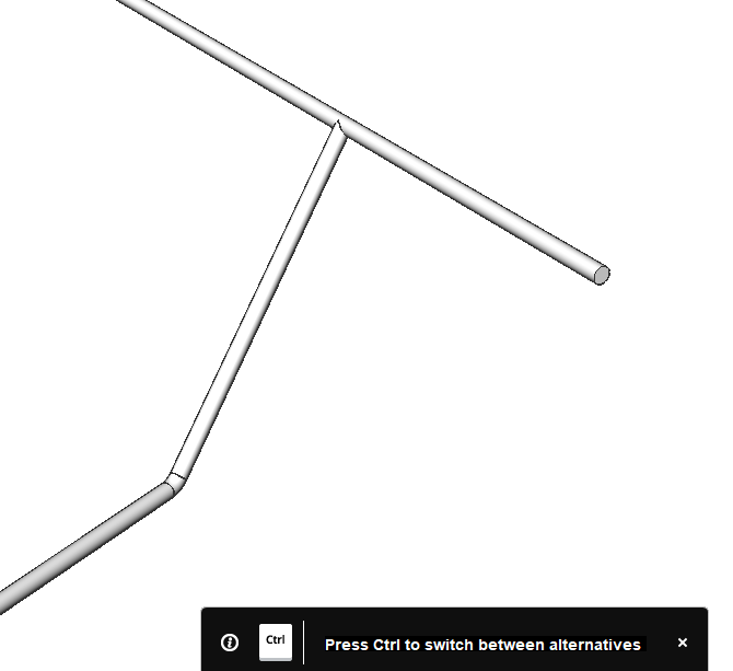
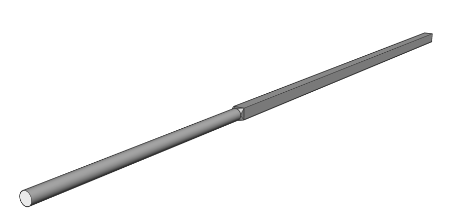
- Wybierz punkt początkowy i narysuj profil. Naciśnij Enter, aby zatrzymać rysowanie za pomocą tego profilu. Twój model powinien wyglądać tak:
- Wyszukaj profil HVAC Round Duct 8'' w panelu BIM Profile i przeciągnij profil do przestrzeni modelu.
- Kliknij koniec profilu prostokątnego po najechaniu kursorem na jego powierzchnię profilu.Uwaga: Aby z łatwością zatrzasnąć koniec profilu prostokątnego, włącz ustawienie Wyświetl osie lub ustaw zmienną systemową DISPLAYAXES na 1.
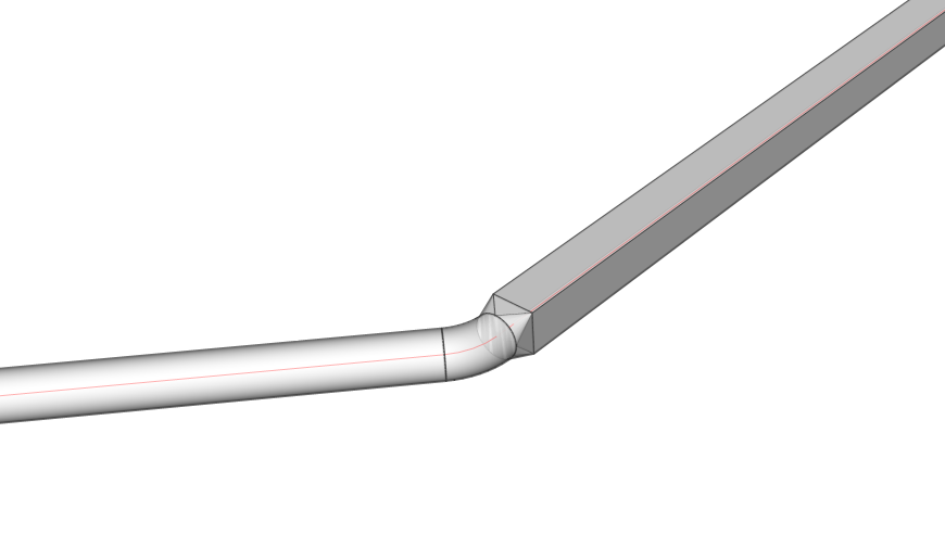
- Upewnij się, że okrągły profil jest rysowany wzdłuż tej samej osi, co prostokątny. Po zaakceptowaniu ostatniego punktu profilu kołowego, zostanie on połączony z profilem prostokątnym poprzez automatycznie wygenerowany reduktor.
Uwaga: Jeśli wybrałeś rysowanie z profilem innym niż HVAC, nie otrzymasz automatycznej klasyfikacji jako Segment przepływu, a połączenie nie zostanie wykonane natychmiast. Nadal można ręcznie sklasyfikować profile za pomocą polecenia BIMKLASYFIKUJ, a następnie użyć BIMPOŁĄCZENIEPRZEPŁYWU, aby połączyć je za pomocą reduktora.Uwaga: Upewnij się, że opcja Wyświetl boki i końce oraz Wyświetl osie jest włączona. - Wybierz łączące się końce obu segmentów.
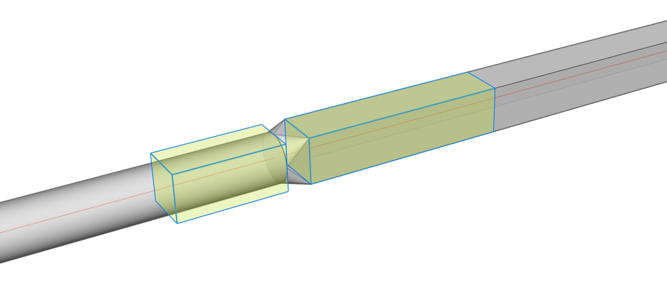
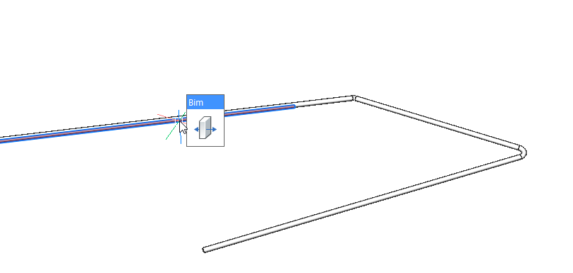
- Uruchom narzędzie BIMROZCIĄGNIJ.
- Najedź kursorem na jeden z boków i kliknij żądaną lokalizację. BricsCAD automatycznie rozciąga 2 segmenty przepływu w ich nowej pozycji i dodaje dodatkowe zakrzywione dopasowanie przepływu pośrodku.