Assembly Design Commands and Tools
Commands
| Icon | Command | Description |
|---|---|---|
 |
BMNEW | Create a new mechanical component as a new drawing file. |
 |
BMMECH | Convert the current drawing into a mechanical main component. |
 |
BMINSERT | Insert an existing mechanical component into the current drawing. |
 |
BMINSERT | Insert an existing mechanical component into the current drawing with automatic resizing of the new part and connecting it to the parent part. |
 |
BMHARDWARE | Open the Components Panel with the Standard Mechanical Components |
 |
BMFORM | Create a new mechanical component and insert it into the current drawing. |
 |
BMCONNECT | Connect 2 Piping standard parts by creation of 3D constraints between their connection entities. |
 |
BMREPLACE | Replace a component insert. |
 |
BMLOCALIZE | Switch external components to local components. |
 |
BMEXTERNALIZE | Switch local components to external components. |
 |
BMOPEN | Open the source drawing of an external mechanical component. |
 |
BMOPENCOPY | Open a copy of a component insert as a new drawing. |
 |
BMDISSOLVE | Dissolve a mechanical component inserted into the current drawing. |
 |
BMLINK | Change target 3D solids of component-based features. |
 |
BMUNLINK | Break the connection between a component insert (e.g. a Window) and a 3D solid (e.g. a Wall) retaining the opening. |
 |
BMHIDE | Hide a mechanical component or subcomponent in the current drawing. |
 |
BMSHOW | Show a previously hidden mechanical component or subcomponent in the current drawing. |
 |
BMVSTYLE | Apply a visual style to a mechanical component. |
 |
BMBALLOON | Create associative balloon entities for assembly components in Model Space and for their generated views in a Paper Space layout. |
 |
BMBALLOON | Allow automatic placement of associative balloons on all components in a particular drawing view in a Paper Space layout. |
 |
BMBOM | Insert the Bill-of-Materials (BOM) table in the current drawing. |
 |
BMMASSPROP | Compute mass properties for the current model using densities assigned to its components. |
 |
BMUPDATE | Reload all referenced components from external files and update BOM tables. |
 |
BMUPDATE | Reload all selected referenced components from external files and update BOM tables. |
 |
BMEXPLODE | Create an exploded representation for an assembly by moving components to make them all visible, store it in a new block, and insert the block in Model Space. |
 |
BMEXPLODEMOVE | Move selected parts to form an exploded representation in a given direction, taking into account possible physical collisions between components (similar to the Linear option of the BMEXPLODE command). |
 |
BMTRAILINGLINES | Create all necessary trailing lines for the selected parts. |
 |
MECHANICALBROWSEROPEN | Display the Mechanical Browser. |
 |
PARAMETERSPANELOPEN | Display the Parameters Manager. |
 |
BMDEPENDENCIES | List all files in the command window, containing component definitions inserted in the assembly. |
 |
BMRECOVER | Recover a broken mechanical structure. |
 |
BMUNMECH | Convert the current mechanical component into a plain drawing. |
| BMXCONVERT | Convert X-Hardware solids in the current drawing into mechanical components. |
Tools
You can use the following tools to work with mechanical components:
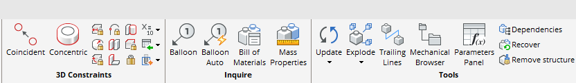
- On the Assembly toolbars:
-
Assembly

-
Assembly Insert

-
Assembly Explode

-
Assembly Visualization
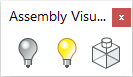
-
-
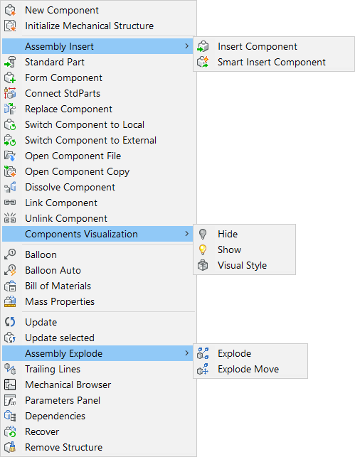
In the Assembly menu (Mechanical Workspace only):
-
On the Assembly tab of the Mechanical Workspace Ribbon:
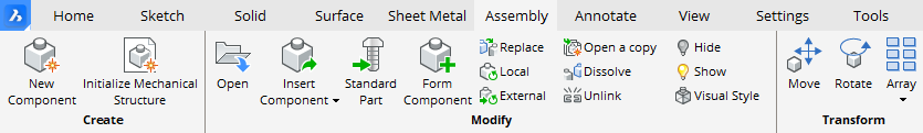
Tools