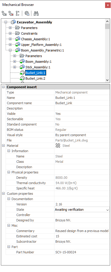
Component properties and context menus are located in the Mechanical
Browser panel.
Component context menus display when you right-click the component. Component properties
display automatically when selecting one or more components in the Mechanical Browser
panel.
Figure 1. Mechanical Browser
Components can be: Main, Insert and Subcomponent. If Mechanical
blocks and entities are enabled, they also will be listed as components in the
browser.
Table 1. Components
Type of component
Rendered visual style
Wireframe visual style
Hidden
Component without subcomponents
*
*
*
Component with subcomponents
*
*
*
Standard part component
Mechanical block
Mechanical external reference
Mechanical entity
* External components contain a green arrow: or .
Table 2. Component Properties
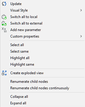
Context menus
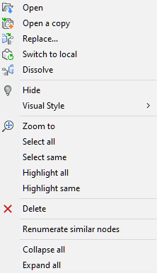
Main Component context menu
Right-click the main component name:
Figure 2. Main Component context menu
Update: updates the hierarchy of
mechanical components for the current drawing in case
referenced drawing files of sub-components have been
modified.
Visual Style: All by
Viewport: applies the current
Visual Style to all
components in the assembly (see the
SHADEMODE command).
Switch all to local: switches all
components to internal components (see the
BMLOCALIZE command).
Switch all to external: switches
all components to external components (see the
BMEXTERNALIZE command).
Add new parameter: creates a new
parameter in the assembly.
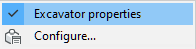
Custom properties: allows to
define custom properties for the drawing. If there are
per-instance property sets, opens a submenu:
Toggle property sets that should be applied to
the root component only, or select Configure to open
a dialog to configure custom properties.
If no
per-instance property sets are present, opens the
BM_PROPERTIES dialog box.
Select all: select all components
with the same definition.
Select same: select all
components with the same name and the same parameter
values.
Highlight all: highlight all
components with the same definition.
Highlight same: highlight all
components with the same name and the same parameter
values.
Create exploded view: create a
block with an exploded representation of the current
assembly.
Renumerate child nodes:
renumerates all child nodes according to their
type.
Renumerate child nodes
continuously: renumerates all child
nodes with continuous numeration when applicable.
For
example, top-level components will get continuous
numbers, but the numeration of their subcomponents
will not be changed.
Collapse all: collapse the main
component and all components and subcomponents.
Expand all: expand the main
component and all components and subcomponents.
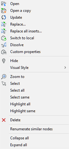
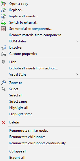
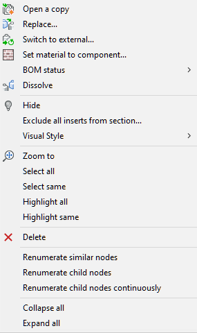
Component context menu
Right-click a component name.
External components context menu
(left), local components context menu (right):
Open: opens the referenced
drawing (see theBMOPEN command).
Open a copy: opens a copy of a
component insert as a new drawing (see the
BMOPENCOPY command).
Update: reloads all referenced
components from external files and update BOM tables
(see the BMUPDATE command).
Replace: replaces a component
insert (see the BMREPLACE command).
Replacing a local insert turns it into an external
insert.
Replace all inserts: replaces all
inserts that refer to the same source (see the
BMREPLACE command). Replacing
local inserts turns them into external inserts.
Switch to local: switches an
external component to an internal component (see the
BMLOCALIZE command).
Switch to external: switches an
internal component to an external component (see the
BMEXTERNALIZE command).
Set material to component:
assigns a physical material to a local component.
Remove material from component:
removes the physical material definition from a local
component.
BOM status: parameter to control
the appearance of the component in BOM tables.
Dissolve: dissolves a mechanical
component inserted in the current drawing (see the
BMDISSOLVE command).
Custom properties: opens a dialog
to configure custom properties.
Unlink: breaks the connection
between a component insert (for example a Window) and a
3D solid (for example a Wall) retaining the
opening.
Hide () /
Show (): hides or shows the
selected component.
Exclude all inserts from section:
sets the Sectionable property of
all similar inserts to NO. Defines
whether an insert is affected by the
VIEWSECTION command.
Visual Style: displays the
Visual Style menu. All Visual
Styles that are saved in the current drawing are
available.
By parent component:
renders the selected component according to the
shademode of the parent component (see the
SHADEMODE command).
All by Viewport: renders
all components according to the current viewport
shademode (see the SHADEMODE
command).
Zoom to: zooms to the selection
set.
Select all: selects all
components with the same definition.
Select same: selects all
components with the same definition and the same
parameter values.
Highlight all: highlights all
components with the same definition.
Highlight same: highlights all
components with the same definition and the same
parameter values.
Delete: removes the selected
component and its subcomponents from the assembly.
Renumerate similar nodes:
renumerates all nodes of the same type and the same
level.
Renumerate child nodes:
renumerates all child nodes with respect to their type
and name.
Renumerate child nodes continuously:
renumerates all child nodes with continuous
numeration, regardless of their names.
Collapse all: collapses the main
component and all components and subcomponents.
Expand all: expands the main
component and all components and subcomponents.
Subcomponent context menu
External subcomponents context menu (left), local subcomponents
context menu (right):
Open: opens the referenced
drawing (see the BMOPEN
command).
Open a copy: opens a copy of a
component insert as a new drawing (see the
BMOPENCOPY command).
Hide () / Show
(): hides or shows the
selected subcomponent.
Exclude all inserts from section:
sets the Sectionable property of all similar
inserts to NO. Defines whether an
insert is affected by command
VIEWSECTION.
Visual Style: see Component
Visual Style.
Zoom to: zooms to the selection
set.
Select all: selects all
components with the same definition.
Select same: selects all
components with the same definition and the same
parameter values.
Highlight all: highlights all
components with the same definition.
Highlight same: highlights all
components with the same definition and the same
parameter values.
Renumerate similar nodes:
renumerates all nodes of the same type and the same
level.
Renumerate child nodes:
renumerates all child nodes with respect to their type
and name.
Renumerate child nodes
continuously: renumerates all child
nodes with continuous numeration, regardless of their
names.
Collapse all: collapses the main
component and all components and subcomponents.
Expand all: expands the main
component and all components and subcomponents.
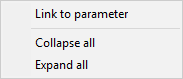
Component parameter context menu
Right-click a parameter:
Link to parameter: create a link
between one or more component parameters and assembly
parameters.
Collapse all: collapse the main
component and all components and subcomponents.
Expand all: expand the main
component and all components and subcomponents.
Properties
Main component properties
Click the main component name:
Figure 3. Main component properties
Name: type a name for the main
component. By default, the name of the main component
equals the file name.
Description: optional description
of the main component.
File: shows the path and name of
the drawing.
Extension type: allows to
identify the component as a BIM Component or a Sheet
Metal Feature.
Insert as: select
Internal Component or
External Component.
Sectionable: defines whether the
component is affected by the
VIEWSECTION command.
Standard component: defines
whether this component is a standard component or
not.
BOM status: defines the behavior
of this component in a BOM table.
Material: material of the main
component.
The Name,
Density, and the optional
Description are defined in
the Physical Materials dialog box.
Select the
Material node and perform
one of the following:
Click the Browse button
() to open the
Physical Materials dialog
box and choose a material in the Project or
Central database list.
The Density property
of the selected material is used by the
BMMASSPROP command.
Click the Delete button
().
The
Material field now reads
<Inherit>. When the
component is inserted in an assembly, the
Material definition is
copied from the main component of the
assembly.
Custom properties: custom
properties assigned by the user, both for all components
and for root component only. Click the Browse
button () to open the dialog to
configure custom properties.
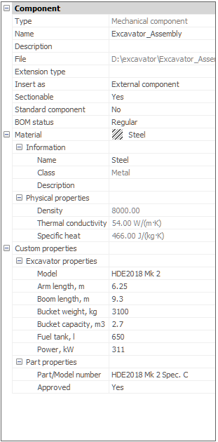
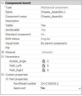
Component insert properties
Click the component name:
Figure 4. Component insert properties
Type: type of the component.
Shows one of the following types: Mechanical
component, Mechanical block or
Mechanical Entity.
Name: type a name for the
component. By default, the name of the component equals
the source file name.
Component name: name of the
component as defined in the source file.
Description: description of the
component as defined in the source file.
Visible: allows to show or hide
the component in the assembly.
Choose between:
Click the Visible
field, click the down arrow button and choose
Yes or
No.
Double-click the
Visible field to toggle the
visibility of the component.
Sectionable: defines whether the
component is affected by the
VIEWSECTION command.
Standard component: defines
whether this component is standard or not.
BOM status: defines the behavior
of this component in a BOM table.
Visual style: allows to control
the visual style for the component. By default, the
visual style is inherited from the viewport.
Click
the Visual style field, click
the down arrow button, and choose a visual style in
the list.
File: shows the path and name of
the referenced drawing.
Material: shows the material of
the component. For top-level inserts of mechanical
blocks or entities, allows to set a material for that
particular instance, therefore overriding the component
material.
If set to
<Inherit>, the material
is copied from the main component.
If the
material is defined explicitly in the source file,
this material is used.
Parameters: shows the insert’s
parameters.
Custom properties: shows the
insert’s custom properties. By default, properties are
inherited from a corresponding component. For top-level
inserts, any of those properties could be overridden
with a desired value.
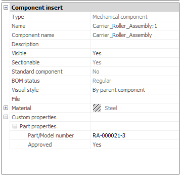
Subcomponent properties
Click the subcomponent name:
Figure 5. Subcomponent properties
Name: name of the component as
defined in the source file of the parent component.
Component name: name of the
component as defined in the source file.
Description: description of the
component as defined in the source file.
Visible: allows to show or hide
the component in the assembly.
Choose
between:
Click the Visible field,
click the down arrow button and choose
Yes or
No.
Double-click the Visible
field to toggle the visibility of the
component.
Sectionable: defines whether the
component is affected by the
VIEWSECTION command.
Standard component: defines
whether this component is standard or not.
BOM status: defines the behavior
of this component in a BOM table.
Visual style: allows to control
the visual style for the component. By default, the
visual style is inherited from the viewport.
Click
the Visual style field, click
the down arrow button, and choose a visual style in
the list.
File: show the path and name of
the referenced drawing.
Material: show the material of
the subcomponent.
If set to
<Inherit>, the material is
copied from the main component.
If the
material is defined explicitly in the source file,
this material is used.
Custom properties: shows the
insert’s custom properties. By default, properties are
inherited from a corresponding component. For top-level
inserts, any of those properties could be overridden
with a desired value.
Selection methods
Select component(s) in the model
The component(s) highlights in the Mechanical Browser.
Click a component in the Mechanical Browser panel
The component highlights in the drawing. Press the space bar to
select the component. If Always synchronize selection option
is enabled in Mechanical browser options setting, then the
component will be selected in the drawing automatically.


 ) /
) /
 ): hides or shows the
selected component.
): hides or shows the
selected component.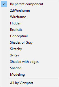
 ) to open the
 ).
).