


Exploded Representations
Overview
Use the BMEXPLODE, BMEXPLODEMOVE, BMTRAILINGLINES, and VIEWBASE commands.
The exploded representation functionality creates associative exploded representations of assemblies and does not modify the assembly itself. Exploded representations are stored in dedicated blocks, which can be edited and inserted according to your needs. You can also generate drawing views from the exploded representations.
Exploded representations are associative. Each part in an exploded representation is linked with the corresponding part in the assembly. Use the BMBALLOON command to update exploded representations to the current state of the assembly, as well as place balloon annotations on the corresponding drawing view(s).
Example of Exploded Representation
Levels of the exploded representation
Exploded representations contain references to the components.
2 levels of exploded representations are supported: Top and Bottom.
-
Top level:
The exploded representation contains references to the top-level components only. Top-level components are components inserted directly into the main assembly. A top-level component in an exploded representation is not exploded further - all its parts and subassemblies remain assembled. A top-level exploded representation allows you to see the basic composition of your assembly.
-
Bottom level:
The exploded representation contains references to the bottom-level components only. Bottom-level components are terminal parts, which do not contain other parts or subassemblies. Bottom-level exploded representations allow you to view all parts in isolation.
Algorithms
BricsCAD provides 3 algorithms to automatically create exploded representations and a manual algorithm.
| Algorithm | Description |
|---|---|
| Table by Type | Create a table-like explosion where components of the same type are grouped in rows. |
| Linear | Find the disassembly sequence of components in a given direction and order the components. Note: This considers possible physical collisions between components. The components can be moved by the algorithm only if there are no other components (not yet moved), that block them. |
| Automatic | Find the disassembly sequence of components with respect to the assembly hierarchy. Note: This considers all possible physical collisions. For each part or subassembly, the direction of movement is identified automatically. |
| Manual | Create an exact copy of the assembly ready for custom edit. In this mode, you can create a custom exploded representation without changing the main assembly. |
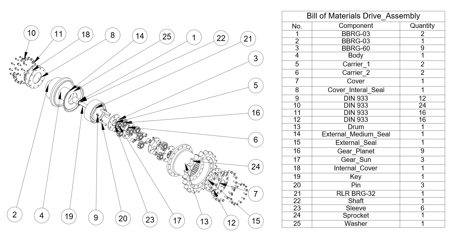
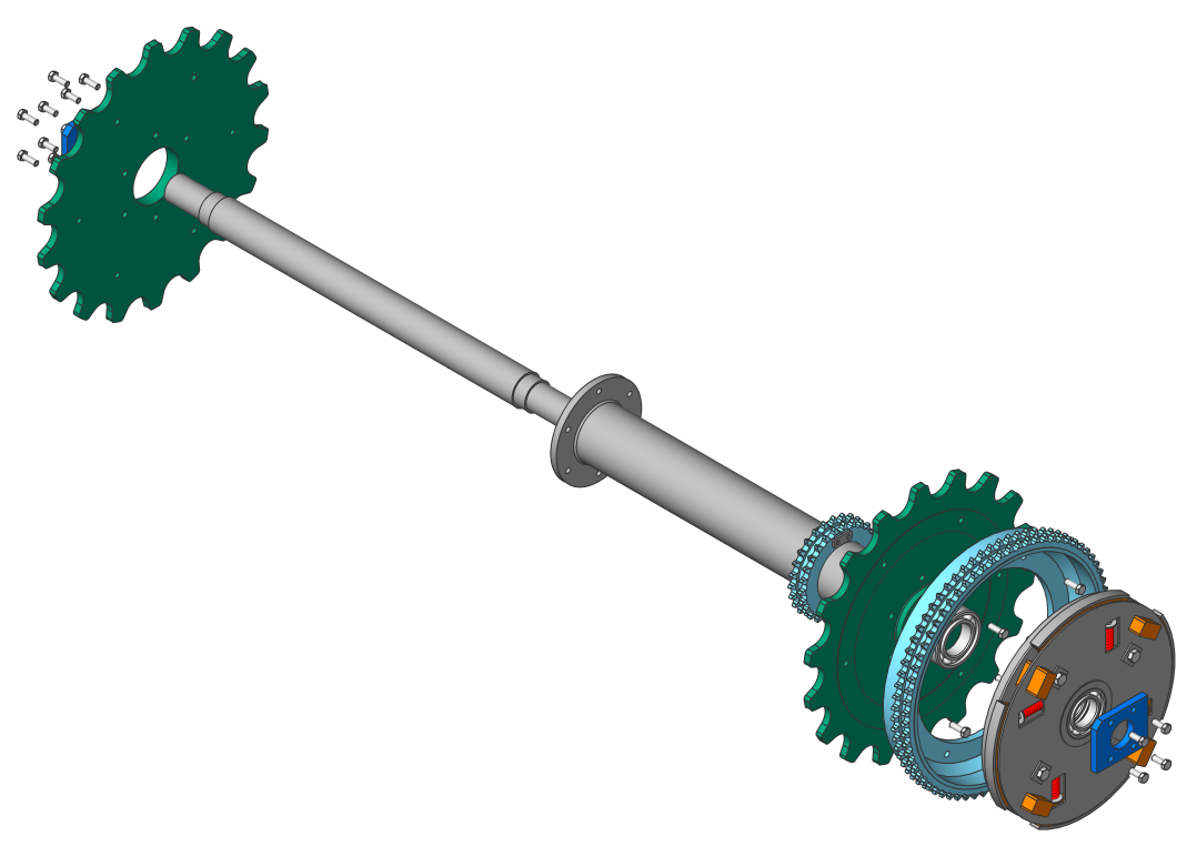
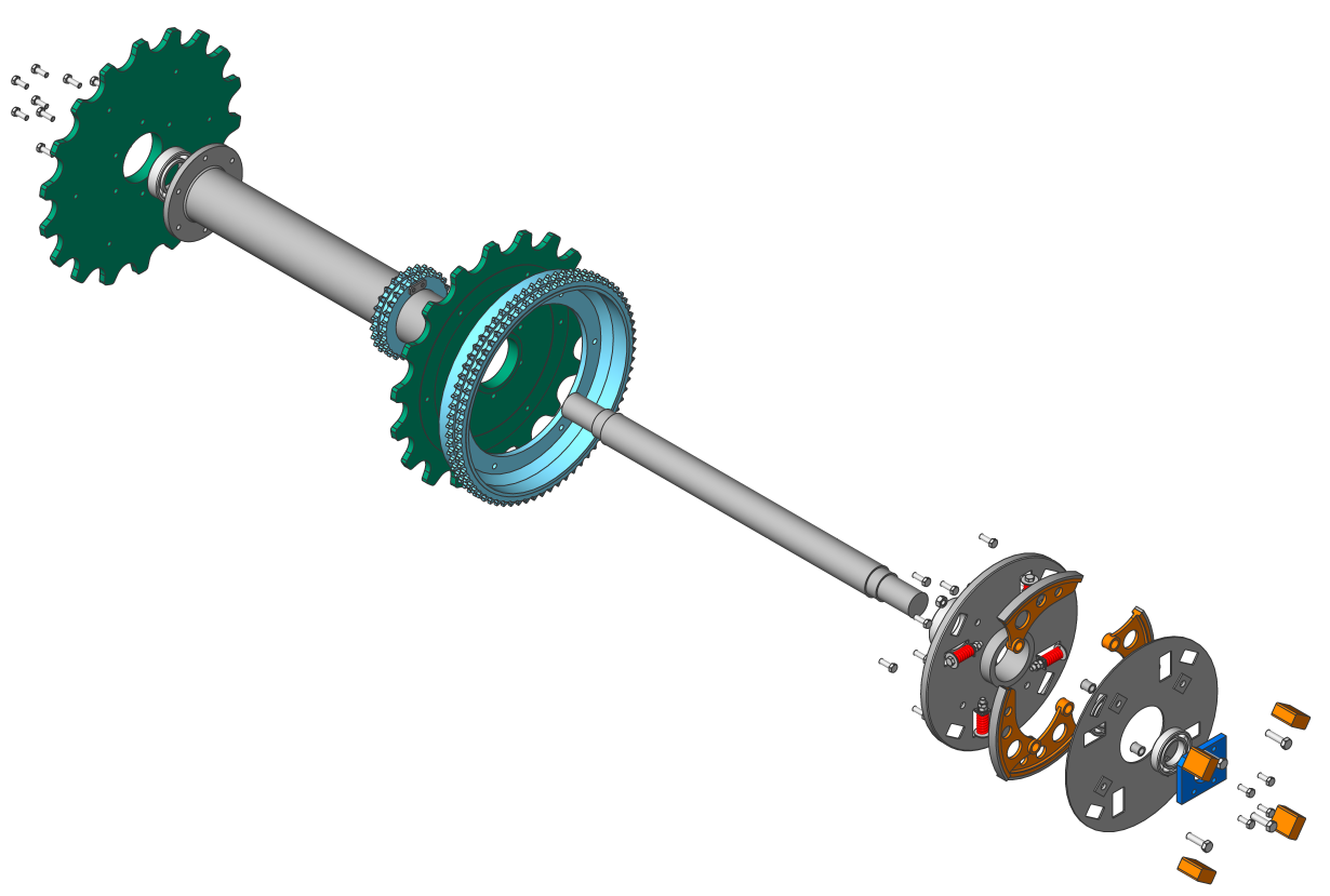
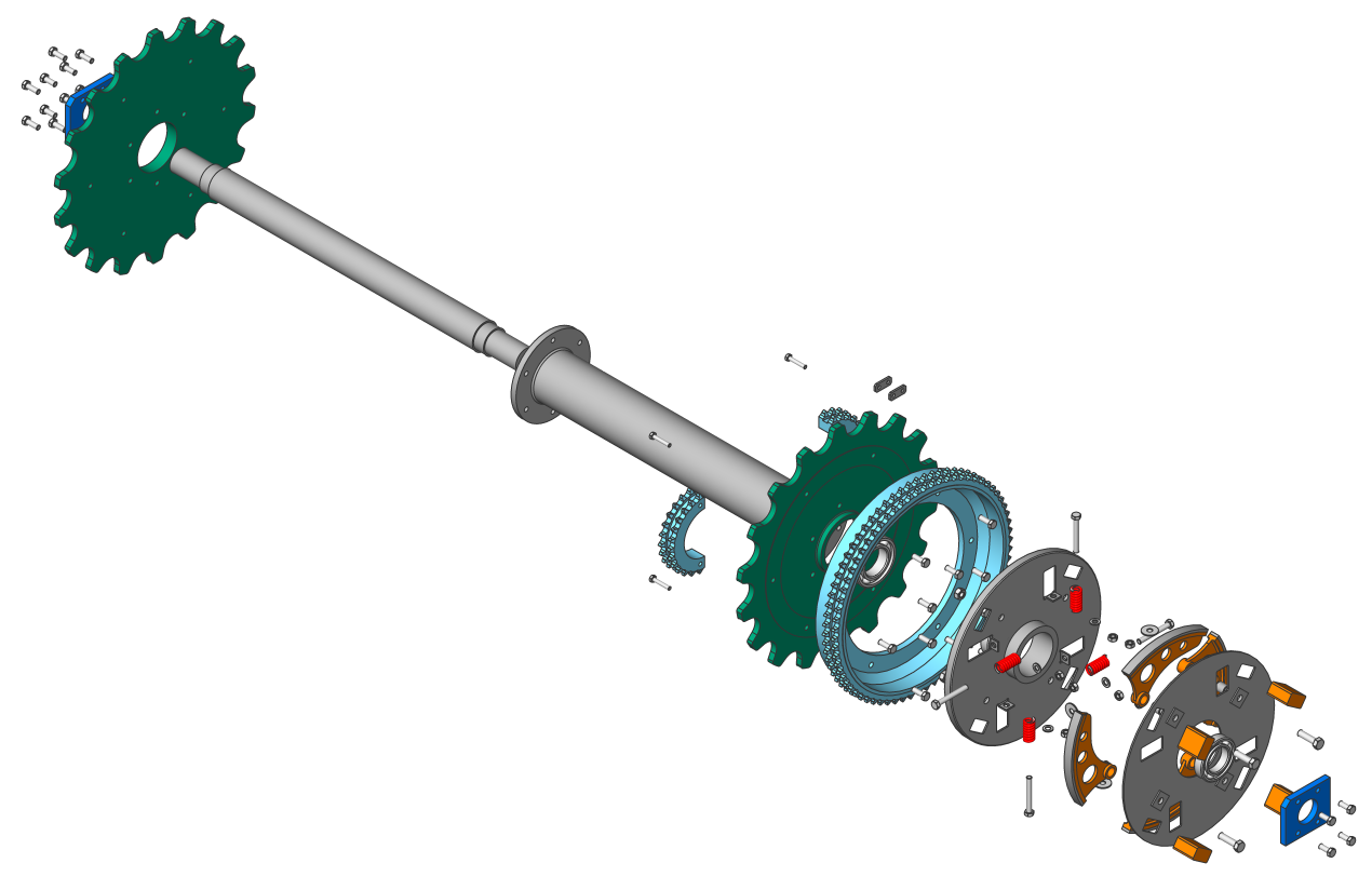
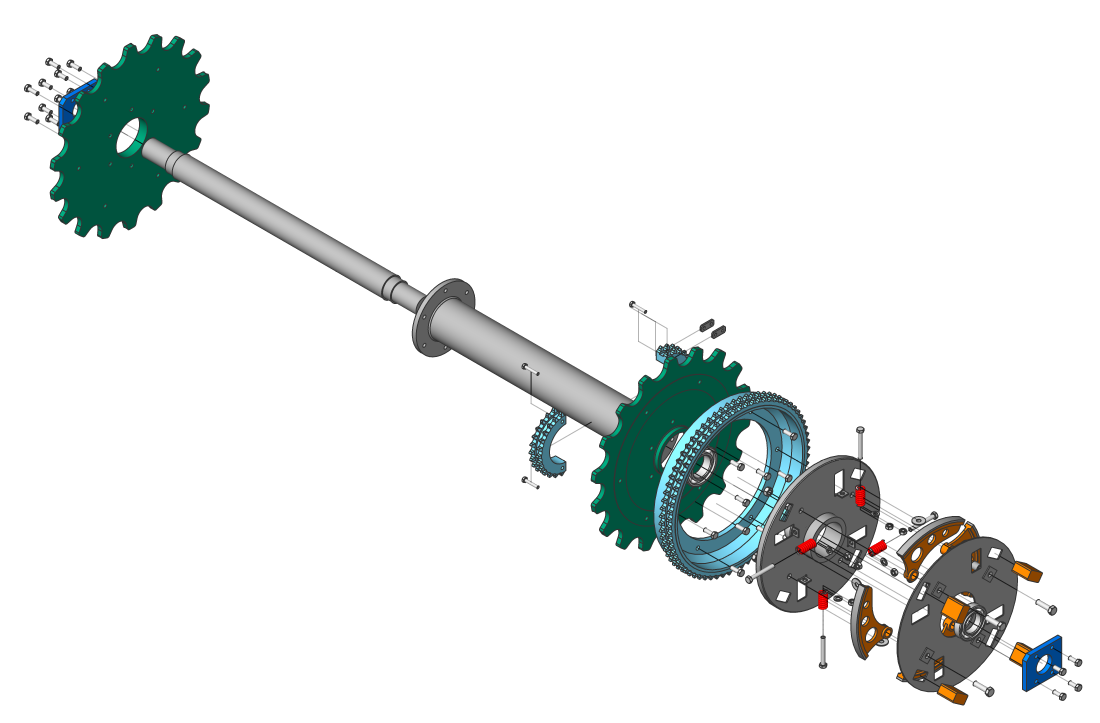
Example: The main drive shaft assembly
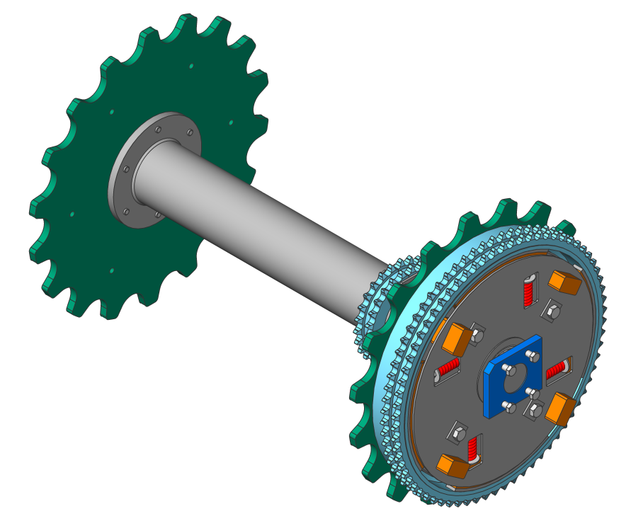
Example: main drive shaft assembly
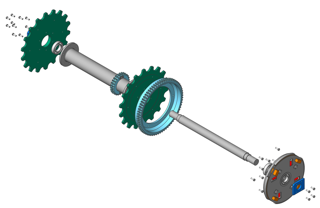
| Table by Type | Linear | Automatic | |
|---|---|---|---|
| Top level | 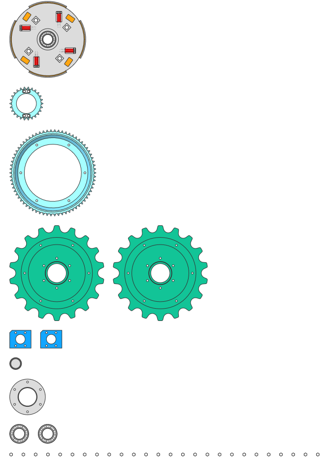 |
 |
 |
| Bottom level | 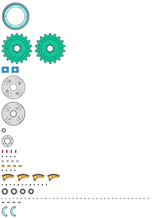 |
 |
 |
Steps and animations
Exploded views may contain one or several steps, which describe a particular assembly or disassembly sequence. Each step corresponds to a set of components that must be moved at this particular stage in order to assemble or disassemble the main assembly. All exploded representation algorithms automatically create all the required steps. You can also delete, merge, split, move, or add extra steps.
Each step has a unique name that can be used to describe the step.
It is possible to animate a particular step, as well as the entire sequence of steps, both indirect and reverse directions (to get disassembly and assembly animations). In order for the animation to work properly, an initial step that defines the initial state of the assembly must be present in the exploded representation. Use the Auto hide property of the exploded representation to automatically hide components that are not important for a particular step during the animation.
Edit exploded representations
Each exploded representation is stored as a block. This allows you to edit the exploded representation with the block editor.
- Right-click the required exploded representation in the Mechanical Browser.
- Select Edit from the context menu.The block editor will open automatically.
- Use the Current step property of the exploded representation in the browser.
- Right-click the desired step in the Mechanical Browser and select Apply from the context menu.
Use the DMMOVE, MOVE, DMROTATE, and BMEXPLODEMOVE commands to move components, inside the exploded representations, to the required positions. The BMEXPLODEMOVE command automatically adds all necessary steps after the current step. For other operations, save the current step after the edit is complete. Only the difference between the current step and the previous one is stored.
It is also possible to change the exploded representation by performing operations on steps.
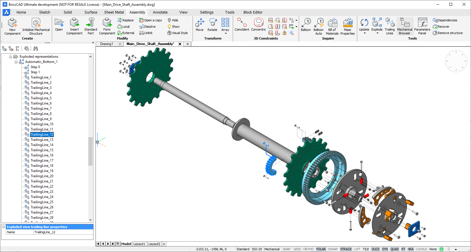
Trailing lines
Trailing lines help explain the relationship between parts. It is a 3D polyline that represents a trajectory and displays the movement of a part during the disassembly process.
Example of trailing lines
Use the BMTRAILINGLINES command to add trailing lines to an exploded representation that is open for edit. This tool creates all trailing lines. The information from the exploded view steps is used to do this.
You can generate trailing lines for all parts or for a subset of parts. For a subset, trailing lines will be built for parts from that subset only, although only necessary trailing lines will be added. Some parts may not have trailing lines at all. You can also manually select 2 parts to add a trailing line between.
When a trailing line is computed, the algorithm automatically determines the location of the part and the location from where the part was removed to compute the trajectory. It considers the movements of both parts.
Each trailing line is displayed in the Mechanical Browser. With the Mechanical Browser, you can see all trailing lines in the model; highlight, select and zoom to parts connected with the selected line; rename or remove the trailing line.
You can edit the trailing line(s) with the standard 3D polyline edit tools.
Exploded view trailing line properties
Create an exploded representation
- Choose one of the following actions to launch the BMEXPLODE command:
-
Click the Explode tool button
 on the Tools panel of the Assembly tab.
 -
Click the Explode tool button
on the Assembly toolbar. -
Select Explode in the Assembly menu.
-
Type BMEXPLODE in the Command line.
-
- If applicable, set the Level and the Name of the exploded representation using the Settings option.
- Select the algorithm. You are prompted: Select exploded view behavior [Edit/Generate drawing views/Finish]:
- Perform one of the following actions:
- Select Edit to edit the exploded representation.
- Select Generate drawing views to generate drawing views of the exploded representation.
- Select Finish to finish the command.
Generate drawing views of the exploded representation
- Launch the VIEWBASE command. You are prompted: Select objects or [Entire model/preseTs/Special views] <Entire model>:
- Select the Special views option. You are prompted: Select view [Exploded view/Unfolded view/Back]:
- Select the Exploded view option. A dialog box to select the exploded representation and the step appears.
- Select the exploded representation. You are prompted: Enter new or existing layout name to make current <Layout1>:
- If applicable, enter the Layout name of the layout for the exploded representation.
- Position the generated drawing views of the exploded representation in the paper space layout.
Update an exploded representation
Run the BMUPDATE command or the Update option of the BMEXPLODE command to synchronize exploded representations with the current state of the assembly.
If applicable, adjust the exploded representation. Such adjustments may be required because of the addition and/or deletion of some parts.
Manage exploded representations
Manage exploded representations
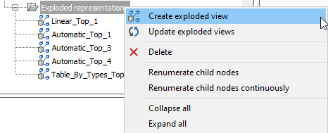
Open the Mechanical Browser to see all exploded representations in the document. All exploded representations will be listed under the Exploded representations group. Open the context menu for the selected exploded representations to see all supported operations in this context:
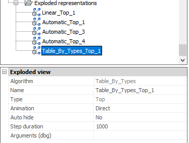
Properties of exploded representations
Each exploded representation has a set of properties. You can edit some of the properties
| Property | Description |
|---|---|
| Algorithm | The name of the algorithm used to create this exploded representation. |
| Name | Name of the exploded representation. This must be unique for all exploded representations, as well as for all the blocks in the model. |
| Type | Type of the exploded representation: Top or Bottom. |
| Animation | The direction of animation. Choose: Direct (from start to end) or Reverse (from end to start). |
| Auto hide | If set to Yes, all unimportant parts for a particular step will be hidden during the animation. |
| Step duration | Default duration of each step during the animation (in milliseconds). The default value is 1000, which is equal to 1s duration. |
| Current step | The current step that corresponds to the state of the exploded representation. |
| Arguments (dbg) | Debug information: full subentity path of one of the entities from exploded view block. |
Operations on exploded representations
The supported operations depend on whether or not the exploded representation is opened for edit.
If the exploded representation is not opened for edit, the following operations are possible:
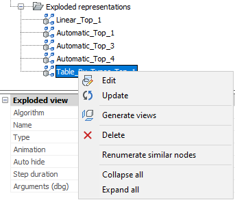
| Operation | Description |
|---|---|
| Edit | Open the exploded representation for edit. Tip: You can also edit the exploded representation with the BEDIT command. |
| Update | Synchronizes the exploded representations with the current state of the assembly. |
| Generate views | Generates views for the exploded representation. |
| Delete | Remove the exploded representation and the associated block from the document. |
| Renumerate similar nodes | Renumerates exploded representation nodes. Each group of nodes with identical names will have their own numeration. |
If the exploded representation is opened for edit, the following operations are possible:
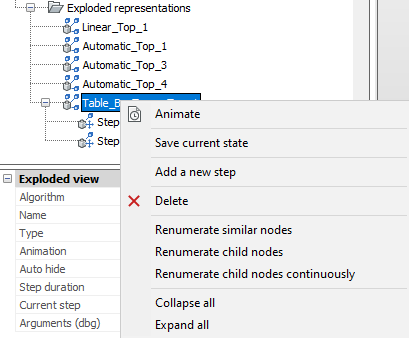
| Operation | Description |
|---|---|
| Animate | Animate the entire sequence of steps. |
| Save current state | Save the current positions of parts in the current step. |
| Add a new step | Add a new step after the last one. Note: The new step will be automatically set as current. All unsaved modifications of the exploded representation will be lost. |
| Delete | Remove the exploded representation and the associated block from the document. |
| Renumerate similar nodes | Renumerates exploded representation nodes. Each group of nodes with identical names will have their own numeration. |
| Renumerate child nodes | Renumerates similar step nodes of current exploded representation. |
| Renumerate child nodes continuously | Renumerates all step nodes of current exploded representation in spite of names. |
In addition, all steps will be listed in the Mechanical Browser for this exploded representation.
Manage exploded representation steps
Open the Mechanical Browser and open the required exploded representation for edit. All steps will be listed under the corresponding node in the tree.
Properties of steps
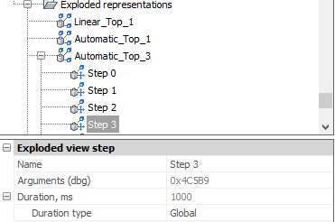
| Property | Description |
|---|---|
| Name | The name of the step. Must be unique for this exploded representation. |
| Arguments (dbg) | Debug information: full subentity path of one of the entities from exploded view block. |
| Duration, ms | The duration of the step. By default, this is equal to the Step duration set for the exploded representation. |
| Duration type | Specify if the duration must be taken from the exploded representation, or if it is specific for this particular step. |
| Duration value (only for Absolute duration type) | The duration for this step in milliseconds. |
Operations on steps
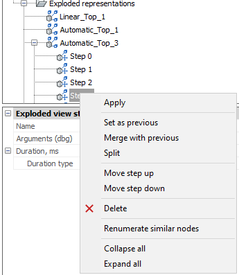
| Operation | Description |
|---|---|
| Apply | Set the step as the current and update the parts in the exploded representation according to this step. |
| Set as previous | Clear the step, so the positions of all parts will be the same as in the previous step. |
| Merge with previous | Merge this and the previous step. The previous step is removed. |
| Split | Split the step to a sequence of steps, each of them corresponding to exactly one part. |
| Move step up | Move the step one position up in the tree. |
| Move step down | Move the step one position down in the tree. |
| Delete | Completely remove the step as well as the associated movements of parts. After that, the positions of parts are updated in the exploded representation. |
| Renumerate similar nodes | Renumerates step nodes. Each group of nodes with identical names will have their own numeration. |
Edit exploded representations
- Select the exploded representation in the Mechanical Browser.
- Right-click the exploded representation and select Edit from the context menu.Note: As an alternative, you can run the BEDIT command and select the block with the exploded representation.
- Perform the necessary operations to get the desired exploded representation.
- Save the current step.
- Save changes using the BCLOSE command with the option Save.
Add trailing lines
- Open the exploded representation for editing.
- Run the BMTRAILINGLINES command.
- Select the subset of parts to create trailing lines for, or select the entire model.
- Select the points of the parts to be used in order to create the trajectory: origin or center.
- If applicable, edit the resulted trailing lines.
- Save changes.