Mechanical browser panel
The Mechanical Browser panel offers a central location to view and modify parametric properties of mechanical parts and assemblies.
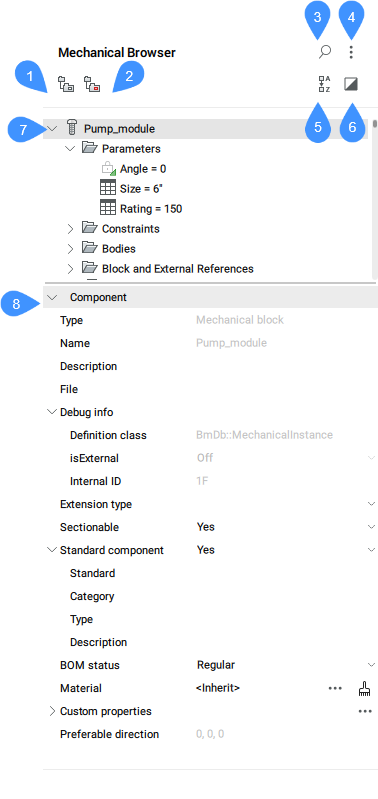
- Group by entity
- Group by type
- Show search
- Settings
- Sort Alphabetically
- Show selected
- Mechanical entities list
- Properties
Group by entity
Groups 3D constraints by entity. Expand an entity to view its associated constraints.
Group by type
Groups 3D constraints by type. Expand a constraint to view the affected entities.
Show search
Opens the search field and the associated tools.
- Search field
- Searches the mechanical browser tree for the character string you enter. The search functions as a filter, so that the browser shows all components whose names (or part of the names) match the character string. Press X on the right of the search field to close the field.
Settings
- Expressions of constraints
- Controls whether the numeric value or the assigned parameter name displays.
- Components parameters
- Controls the visibility of sub-component parameters.
- Expressions of components parameters
- Controls the visual representation of sub-component parameters: numeric value or assigned parameter name.
- Sub-components of standard parts
- Controls the visibility of sub-components of standard parts which are mechanical assemblies.
- Arrays of entities
- Toggles the display of Array nodes in the browser tree, including Components arrays.
- Block and External references
- Toggles the display of Blocks and External References nodes in the browser tree. Also toggles node building in the Bodies folder for Block entities.
- Always synchronize selection
- Toggles the synchronization of the selection nodes in the Mechanical Browser with the selection of the corresponding objects in the model space. When an object is removed from a selection, only nodes corresponding to the objects remaining in the selection remain selected. If no objects are selected, the root node will be selected (similarly to when a document is open).
Sort Alphabetically
Lists mechanical components and 3D constraints alphabetically. Otherwise, they are listed in the order they are added to the assembly.
Show selected
When enabled, only nodes corresponding to selected objects or their parents are displayed.
When enabled and no objects are selected, or selection is cleared, the full model is shown in the browser.
The state of the Show selected mode is remembered between sessions, and is the same for all opened documents.
Mechanical entities list
Displays a hierarchical tree list of mechanical entities, such as user parameters, constraints, parts, arrays and features. Top-level nodes can have sub-nodes. For example, constraint node have sub-node(s) for its argument(s). An array node has sub-nodes for its arguments, etc.
Double click a node to expand or collapse it, double click (click-pause-click) a node to edit its label if applicable. Not all node names can be edited.
Each node in the list has associated context menu. Right-click a node to invoke the menu. The content of the menu can be different for each kind of node. You can also select a group of nodes and invoke a context menu for them. The menu will contain only those elements which are applicable to each selected node.
Context menu for the root component contains the following items:
- Update
- Updates the hierarchy of mechanical components for the current drawing in case the referenced drawing files of sub-components have been modified.
- Visual style > All by Viewport
- Applies the current visual style to all components in the assembly.
- Switch all to local
- Converts all external components in the model to local components.
- Switch all to external…
- Switches all internal components to external components.
- Add new parameter
- Creates a new parameter in the assembly.
- Custom properties
- Opens the Mechanical Properties dialog box to define custom properties for the drawing.
- Select all
- Selects all components with the same definition.
- Select same
- Selects all components with the same name and the same parameter values.
- Highlight all
- Highlights all components with the same definition.
- Highlight same
- Highlight all components with the same name and the same parameter values.
- Create exploded view
- Creates a block with an exploded representation of the current assembly.
- Renumerate child nodes
- Renumerates all child nodes according to their types.
- Renumerate child nodes continuously
- Renumerates all child nodes with continuous numeration when applicable.
- Collapse all
- Collapses the main component and all components and subcomponents.
- Expand all
- Expands the main component and all components and subcomponents.
Context menu for child (non-root) components, internal or external, also offers:
- Open
- Opens the referenced drawing (see the BMOPEN command).
- Open a copy
- Opens a copy of a component insert as a new drawing (see the BMOPENCOPY command).
- Update
- Reloads all referenced components from external files and updates BOM tables (see the BMUPDATE command).
- Replace…
- Replaces a component insert (see the BMREPLACE command).Note: Replacing a local insert turns it into an external insert.
- Replace all inserts...
- Replaces all inserts that refer to the same source (see the BMREPLACE command).
- Switch to local
- Switches an external component to an internal component (see the BMLOCALIZE command).
- Switch to external
- Switches an internal component to an external component (see the BMEXTERNALIZE command).
- Dissolve
- The selected feature is removed from the part, but it will keep its geometry. However, the design intent (spatial and parametric relationships between the feature’s faces) associated with the geometry of a dissolved feature is removed.
- Hide / Show
- Hides / Shows the component.
- Visual Style
- Sets a visual style for the component.
- Zoom to
- Zooms to the selection set.
- Select
- Selects the component.
- Select all
- Selects all components with the same definition.
- Select same
- Selects all components with the same definition and the same parameter values.
- Highlight all
- Highlights all components with the same definition.
- Highlight same
- Highlights all components with the same definition and the same parameter values.
- Delete
- Analogue to the SMDELETE command. In this case, the feature is removed from the browser and the geometry is changed depending on the type of the feature.
- Set material to component
- Opens the Physical Materials dialog box, which allows you to assign a physical material to the component.
- Remove material from component...
- Removes the physical material definition from a local component.
- Make component standard / Make component non-standard
- Changes the type of the component.
- Include all inserts to section
- Sets the Sectionable property of all similar inserts to YES. Defines whether an insert is affected by the VIEWSECTION command.
- Exclude all inserts to section
- Sets the Sectionable property of all similar inserts to NO. Defines whether an insert is affected by the VIEWSECTION command.
- Renumerate similar nodes
- Renumerates all nodes of the same type and the same level.
- Component's BOM status
- Controls the appearance of the component in BOM tables.
Context menu for Parameters contains additional tools:
- Geometry-driven
- If ticked, it makes the parameter geometry-driven.
- Create design table
- Creates a design table to drive parametric block parameters.
- Animate
- Animates models by means of parameters.
Context menu for Component parameters contains additional tools:
- Link to parameter
- Links subcomponent parameter to the main level parameter.
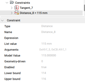
Context menu for Constraints contains additional tools:
- Enabled
- Toggles the enabling of the constraint.
- Flip side
- Flips the side of the constraint (not available for fix constraints).
- Select geometry
- Selects the entities involved in the constraint.
Context menu for dimensional Constraints contains additional tools:
- Geometry-driven
- If ticked, it makes the constraint geometry-driven.
- Create design table
- Creates a design table to drive parametric block parameters (see the Parameters Manager panel).
Context menu for constraint arguments contains additional tools:
- Replace...
- Replaces the current argument with a another one (see the DMCONSTRAINT3D command).
- Exclude
- Excludes the current argument.
Properties
Displays the properties of the selected item(s). If several nodes are selected in the tree, the Properties section displays the properties of all the selected nodes. Changing a property modifies all the selected nodes.
Change a property by clicking a numeric field to edit its value or by selecting another option from the drop-down list, which is opened when you press the down arrow from the right side of the field.
The most important properties of a mechanical block are:
- Extension type: defines the extension type for the mechanical block.
- Sectionable: defines if the mechanical block is sectionable.
- Standard component: defines if the mechanical block is a standard component.
- BOM status: defines the BOM status.
- Material: defines the material.Note: Click the browse button (
 ) to open the Physical Materials dialog box.
 - Custom properties: displays the custom properties.Note:
- Click the browse button () to open the Mechanical Properties dialog box.
- Click the Clear material button to remove the material.
- Click the browse button (
- Preferable direction: indicates the direction for exploded views, which is set with the BMEXPLODECONFIG command.