


Modelowanie powierzchni
BricsCAD® Mechanical provides a powerful toolset for surface modeling and conversion of 3D solids to surfaces and vice versa.
Surface Modeling tools are available on the Surface tab of the Mechanical workspace ribbon:

Surface Modeling and Solid Modeling are similar tools concerning editing and applying 3D constraints. The only difference is that surface Extrude/Revolve/Loft/Sweep tools can create surface entities from closed 2D profiles and also accept non-cloned profiles.
The Region tool can create a region entity from a closed 2D profile and regions can be stitched together to create a larger surface.
Other methods to create a surface are to extract one or more adjacent faces of a 3D solid/surface, and to explode a 3D solid into a set of surfaces and regions.
Surface properties
Surface properties can be accessed or modified through the Propertiespanel. In case a surface is selected, several main tabs are available.
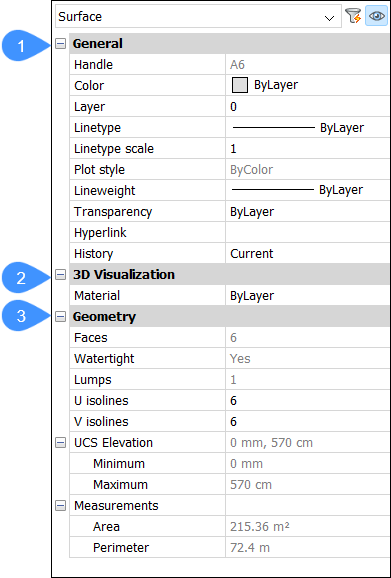
- General
- 3D Visualization
- Geometry
- General
- Describes properties that are applied to the selected entities and are valid for almost any type of entity.Note: For more information about the General properties, see the Properties panel article.
- 3D Visualization
- Describes the materials assigned to the selected entities.
- Geometry
- Describes the geometric characteristics of the selected entities. In case of a surface, several options are available.
-
- Faces
- Describes the amount of faces the selected surface contains.
- Watertight
- Defines whether the surface is watertight or not.
- Lumps
- Defines the amount of lumps display.
- U Isolines
- Defines the amount of horizontal isolines to display.
- V Isolines
- Defines the amount of vertical isolines to display.
Note: The isolines properties are editable in the properties panel, allowing to modify the number of contour lines that are displayed on the curved surfaces. As an example, both isoline properties were set to 3 in the left figure, while 6 was entered in the right figure.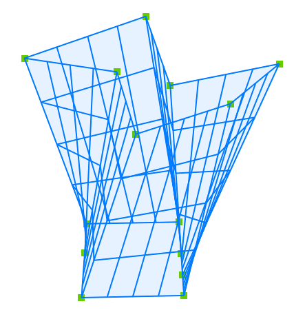
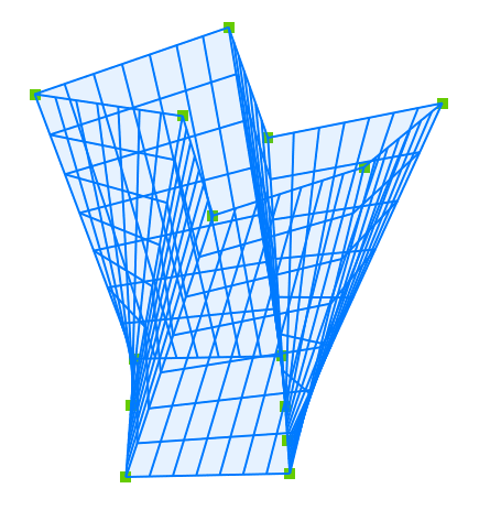 Note: Isolines are only visible in the visual styles Wireframe, 2D Wireframe and X-Ray.
- UCS Elevation
- Defines the elevation of the upper and lower extend of the surface compared to the Unified Computing System.
- Measurements
- Specifies measurements of the selected surface such as area and perimeter.