Creating Flanges
Overview
- Create a base flange from a closed 2D profile, which defines its boundary.
- Create one or several edge flanges by pulling edges of existing flanges.
- Create several flanges at once by extruding a 2D polyline (every linear edge of the polyline becomes a flange).
- Flanges can be created as elements of lofted sheet metal parts. See Creating and Splitting Lofted Bends.
- Flanges can be recognized in existing geometry. See Converting to Sheet Metal and Repairing.
In contrast to history-based MCAD, BricsCAD applies the same set of tools to modify any flange - independently.
Create a Base Flange
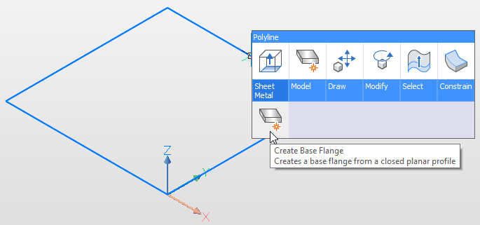
In general, you create a base flange to start your sheet metal part design. To create a base flange, select a closed planar profile and run the SMFLANGEBASE command.
- Click the Create Base Flange tool button (
 ) on the Sheet Metal toolbar.
 - Choose Create Base Flange in the Sheet Metal menu.
- Choose Create Base Flange in the Sheet Metal group of the Quad cursor menu:
Create a Base Flange
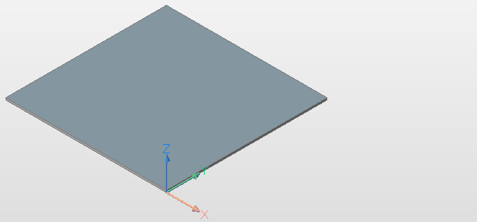
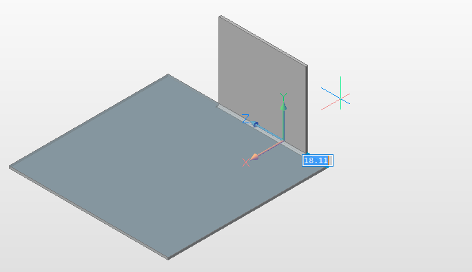
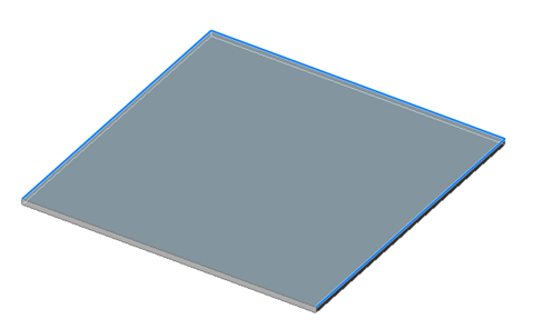
To create a base flange the SMFLANGEBASE command extrudes a profile.
The height of the base flange is the default Thickness property of the sheet metal part. To change the thickness of your sheet metal part, type the appropriate value in the Thickness field of the Mechanical Browser.
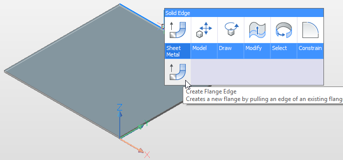
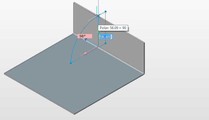
Create Edge Flanges
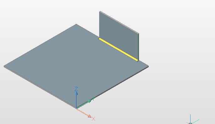
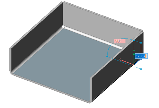
- Select a linear edge.
- Select the SMFLANGEEDGE command in the Sheet Metal section of the Quad cursor menu.
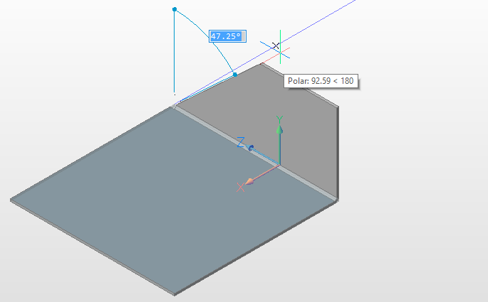
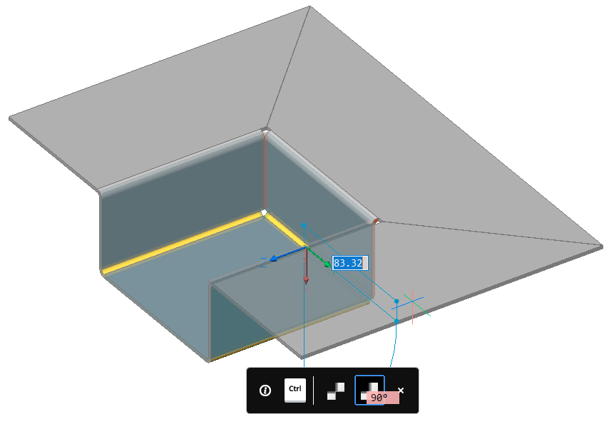
- Move your mouse pointer to define the desired length of the edge flange and the angle between the 2 flanges. You can also use the dynamic dimensions fields to enter the required values.
Create Flange Edge
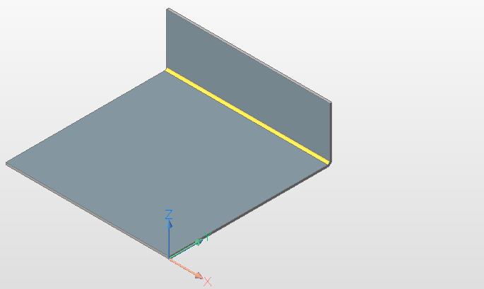
To create an edge flange where the width is different to the width of the edge, select the Width option of the SMFLANGEEDGE command and define the offset distance from one or both sides of the edge.
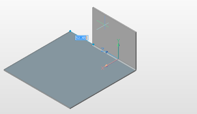
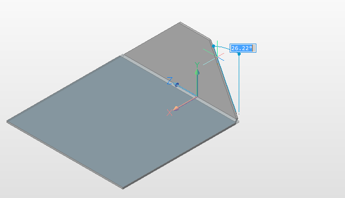
Create Edge Flange with Taper Angle(s)
You can create trapezoidal edge flanges with the Taper angle option of the SMFLANGEEDGE command:
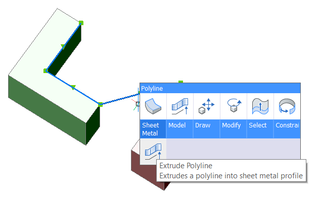
Create Multiple Flanges by Extruding a Polyline
There is a simple but important class of sheet metal parts which are seen as a thickened polyline if we view on the part from the "front" side:
- use sequential calls of the SMFLANGEEDGE command, or
- draw a polyline and use the DMEXTRUDE command, followed by the DMTHICKEN, SMCONVERT, and SMBENDCREATE commands.
BricsCAD allows you to draw a part in a complex assembly with other parts so that it does not interfere with other entities in the assembly.
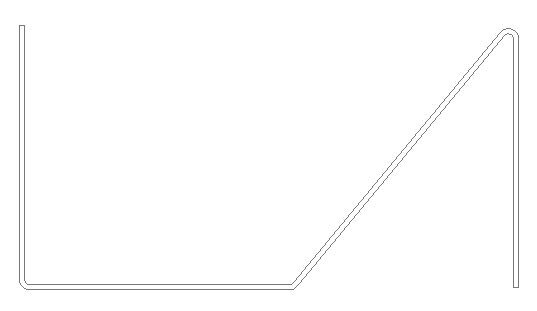
- Draw a polyline that represents a sketch of the future sheet metal part:
 Do one of the following:
- Click the Extrude Polyline tool button (
 ) on the Sheet Metal toolbar.
 - Choose Extrude Polyline in the Sheet Metal menu.
- Choose Extrude Polyline in the Sheet Metal group of the Quad cursor menu:
- Click the Extrude Polyline tool button (
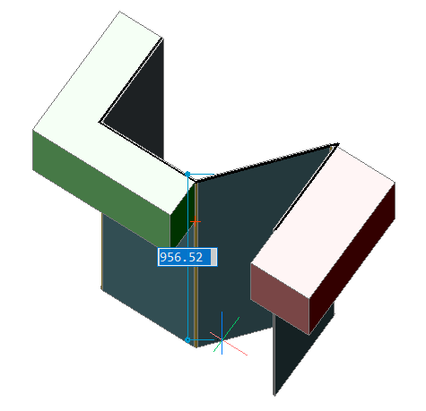
- Hover your cursor to select extrusion height or enter the value and press Enter to accept:
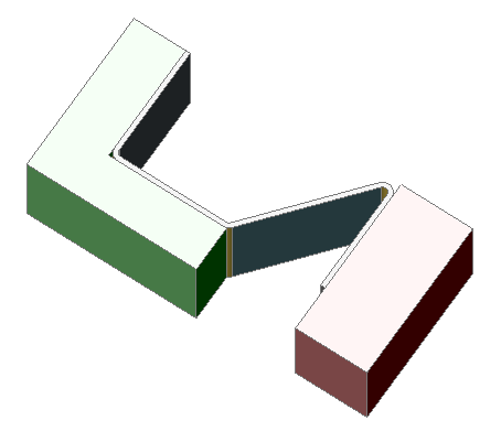
 The body is created and the extensions are respected. The sheet metal part does not exceed the dimensions of the original polyline. The behavior is the same, even with different thicknesses:
Thickness 1 mm Thickness 2 mm Thickness 4 mm 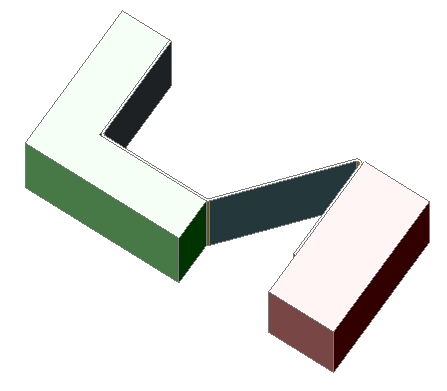
Extrude a Contour to Create a Flange
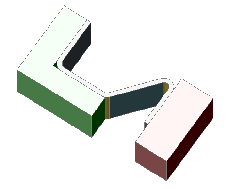
The SMFLANGECONTOUR command allows you to extrude a given contour to a new flange and attach it to the model. It can be thought of as a sequence of the SMFLANGEBASE, SMFLANGECONNECT, and SMBENDCREATE commands. In reality, it intelligently chooses the thickness faces on selected flanges and connects them with the thickness faces on a new flange.
- Click the Create Flange from closed Contour tool button (
 ) on the Sheet Metal toolbar.
 - Choose Create Flange from Contour in the Sheet Metal menu.
- Choose Create Flange from Contour in the Sheet Metal group of the Quad cursor menu:
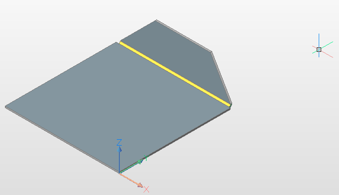
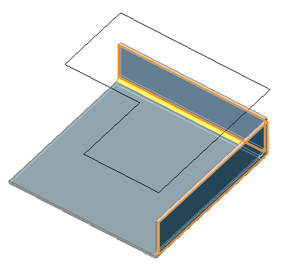 Once all the required flanges are selected, click on the contour:
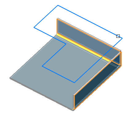 The command creates a new flange and merges it with the selected flanges on the part:
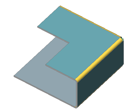
Bends, Corner Reliefs and Junctions
Create Multiple Flanges
You can create several flanges simultaneously.
- Select multiple edges, then choose Create Flange Edge (
 ) in the Sheet Metal command group of the Quad cursor menu.
 - Launch the SMFLANGEEDGE command and select multiple edges.
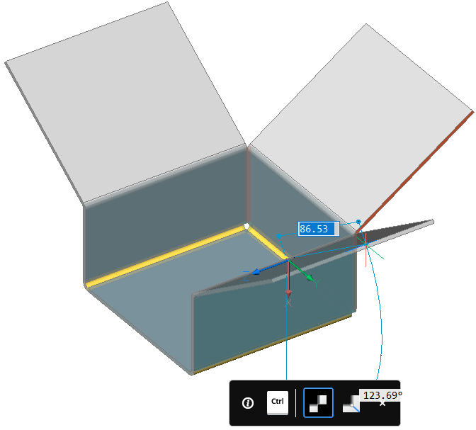
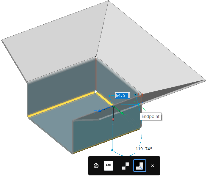
- Create the edges dynamically.Define the angle and the flange height using the dynamic entry fields. Press the TAB key to switch between the Angle and the Distance field.
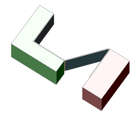
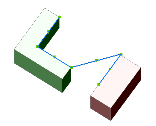
- Select the inside edges of the newly created flanges:
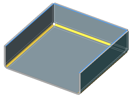
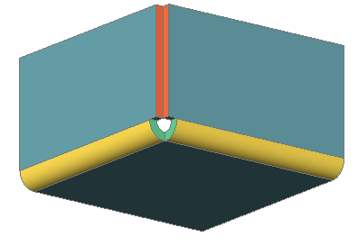
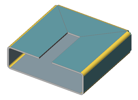
- Create the flanges. The command automatically calculates the intersection of the flanges and creates a junction or miter features. At 90 degrees miters are created:
 For other angles junctions are created:
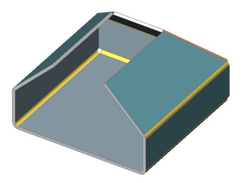 In all cases material conflicts are avoided:
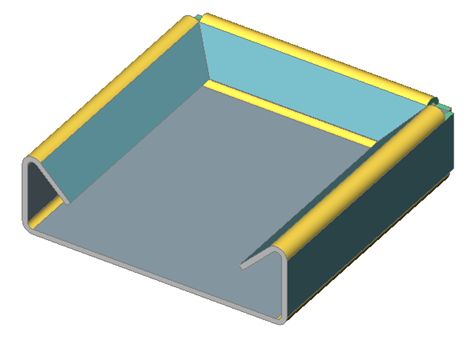 If the flanges are created externally, use the Toggle option (as well as widget control) to control the connection type for miters:
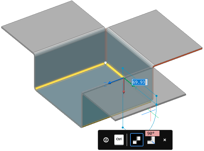
 and junctions: