Sheet Metal Design Methods
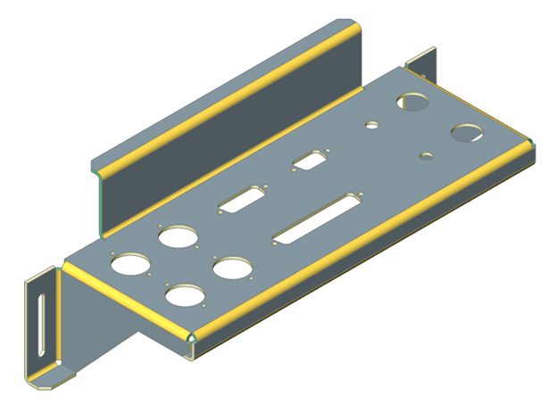
Sheet metal design allows you to model sheet metal parts and generate their unfolded representations with manufacturing information.
You can create complex sheet metal parts with BricsCAD easily and rapidly because the design process is different from a manufacturing process. Do not think in terms of a planar sheet that should be cut and bent, but model your part directly as you create solid bodies with Direct Modeling tools.
-
Create a base flange from a closed planar profile, then add flanges:
- Pull its edges to create additional edge flanges with bends.
- Create partial flanges with automatic creation of the corresponding bend reliefs.
- Pull several adjacent edges to create several flanges at once with automatic creation of corner reliefs and junctions between them.
- Bend a flange to create a new flange with a bend from its portion.
-
Create a combination of flanges and lofted bends connecting two 3D profiles.
Use the Sheet Metal Loft tool.
-
Create a combination of flanges and bends from a planar profile.
Use the Sheet Metal Extrude tool.
-
Create a shelled body from a 3D solid.
Use Shell option of the SOLIDEDIT command with the desired thickness, then convert it to a sheet metal part with the SMCONVERT command, and create bends and junctions from its hard edges.- Make holes by drawing closed profiles on faces of the flanges and pushing them through the flanges.
- Adjust material thickness and bend radius using predefined parameters.
- Apply Direct Modeling operations and 3D constraints to further adjust your design while always maintaining the design intent in terms of sheet metal features.
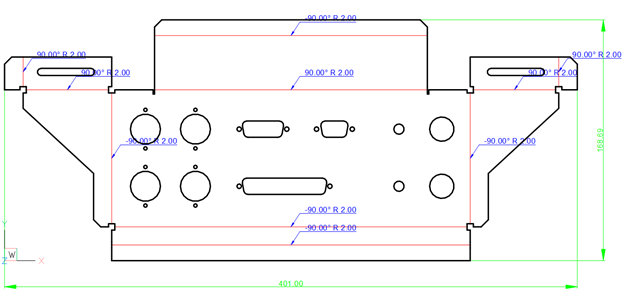
- Automatically generate unfolded representation of your part and send it to a CAM system by exporting the corresponding 2D drawing with bend annotations in a .dwg or .dxf file.
- Make holes by drawing closed profiles on faces of the flanges and pushing them through the flanges.
- Insert Form Features from a library. A library of parametric form features is installed with BricsCAD Sheet Metal and you can create your own form features.
- Create rib form features from a 2D curve lying on the flange by the SMRIBCREATE command.
- Adjust material thickness and bend radius using predefined parameters.
- Apply Direct Modeling operations and 3D constraints to further adjust your design while always maintaining the design intent in terms of sheet metal features.
When your sheet metal part is ready, you can automatically unfold it and send the result to a manufacturing engineer by exporting the corresponding 2D drawing.