


Unfolding Sheet Metal Parts and Exporting to CAM
Overview
Use the SMUNFOLD command.
Sheet metal parts can be designed in many different ways. To manufacture the sheet metal part, a flat pattern with bend annotations is needed, which is then used in a CAM system to program CNC machines, such as laser cutters and press brakes. This flattening operation is called unfolding.
Unfolding a sheet metal body
The SMUNFOLD command unfolds sheet metal parts. BricsCAD automatically creates a solid body corresponding to the flat metal sheet needed to manufacture the sheet metal part using bending techniques. This sheet is placed on the XY-plane and is oriented along the coordinate axes similarly to the orientation of the initial body in 3D space. To change the orientation of the unfolding in Z axis, run the SMUNFOLD command again and select the opposite face of the initial body.
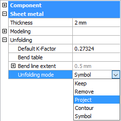
Form features are unfolded according to the Unfolding Mode setting in the Mechanical Browser.
The options are:
- Keep (0): allows to keep form features geometry on the unfolded representation.
3D model and unfolded body 2D 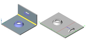
- Remove (1): removes the form feature geometry from the unfolded representation.
3D model and unfolded body 2D 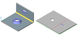
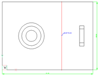
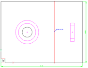
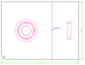
- Project (2): generates a form feature symbol by projecting the form feature edges onto the flange plane.
3D model and unfolded body 2D 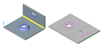
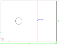
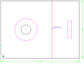
- Contour (3): generates a form feature symbol by projecting the external contour and holes of the form feature onto the flange plane.
3D model and unfolded body 2D 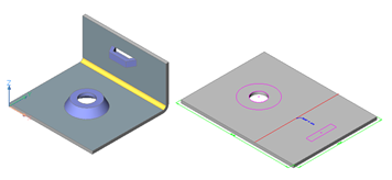
- Symbol (4): creates the unfold symbol on the UNFOLD_SYMBOL_UP or UNFOLD_SYMBOL_DOWN layer depending on the direction of the form feature.
3D model and unfolded body 2D 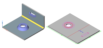
The unfold mode for the current sheet metal part can be set in Mechanical Browser.
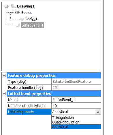
Lofted bends lying on cylindrical and conical surfaces can be unfolded analytically: the dimensions and shape of the unfolded lofted bend will be as if its middle surface was mathematically unrolled on the plane. This shape can also be achieved by a highly increased number of samples for the lofted bend. You must set the Unfolding mode individually for each lofted bend feature. If analytical unfolding is allowed, the option will be present in a drop down list:
To unfold a sheet metal body
- Launch the SMUNFOLD command.You are prompted: Select a flange or lofted bend face to start unfolding [Associative]:
- Select a face on sheet metal part.You are prompted: Select position of the unfolded body:
- Specify a point.You are prompted: Validate the unfolded body and select an option [save 2D geometry/save 3D geometry/Optimize bend annotations/Keep] <Keep>
- Do one of the following:
- Save the unfolded 3D solid in a separate drawing file.
- Convert the unfolded 3D solid to a 2D drawing file (*.DWG or *.DXF).
- Rearrange the bend annotations.
- Keep the block with the unfolded part in the sheet metal part model.
The SMUNFOLD command considers the deformation of the sheet metal material during bending. When a flat sheet of metal is bent into a 3D part with a bending tool (for example a press brake), the material is plastically deformed, which means it is compressed at the inside of the bend and stretched at the outside. As a result, the length of the part measured along its surface is different in the flat and bend states. BricsCAD can automatically compute the proper unfolded length of your part based on the material deformation properties. These properties can be defined by setting the value of K-Factor parameter or by attaching a Bend Table.
Managing layer properties of the 2D geometry
The 2D geometry generated by the SMUNFOLD, SMEXPORT2D, and SMASSEMBLYEXPORT commands has different colors for contours, bend lines up, bend lines down, overall dimensions, form features up, form features down, bend annotations and attributes.
You can set the colors differently in the Sheet Metal/Commands/Layers for unfolding settings group on the Settings dialog box. Each entity type is placed on a dedicated layer of which the color is controlled through a series of user preferences:
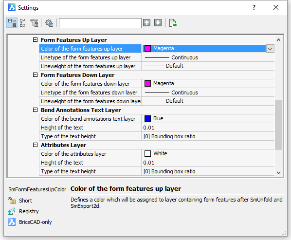
If the 2D geometry of a form feature was taken from a library component, its properties are controlled by the properties of this component at the moment of insertion. There are 2 other modes of Unfolding Mode which lead to generation of 2D geometry for form features: Project or Contour. In these modes 2D geometry is generated automatically from 3D geometry and its appearance is controlled by Form Features Up Layer and Form Features Down Layer settings groups.
To export a sheet metal body
Sheet metal parts created or edited in BricsCAD can be processed by different CAM systems (such as JETCAM or CADMAN-B) to generate NC code for cutting and bending machines.
The user preference controls the save 2D geometry option of the SMUNFOLD command to customize the .DXF file to be compatible with the list of popular CAM systems.
The SMEXPORT2D command exports the unfolded representation of a sheet metal body as a 2D profile in *.DXF or *.DWG file format.
The SMEXPORTOSM command exports a sheet metal solid to the *.OSM (Open Sheet Metal) file format (native for the CADMAN-B CAM system).
To export an assembly with sheet metal parts to .DXF
The SMASSEMBLYEXPORT command searches the assembly tree for sheet metal design and exports it to a *.DXF file. As a result, a set of *.DXF files, sorted by thickness in different subfolders is created in the output folder. The command generates a HTML report which allows to control the output. Most of the sheet metal parts will be processed automatically. Poor sheet metal parts will be reported by the command to be reworked manually.