


Praca z Zagięciami i Złączeniami
Dwa sąsiednie kołnierze części arkusza blachy są połączone gięciem lub złączem. W odróżnieniu od wielu innych mechanicznych systemów CAD, zagięcia i połączenia są oddzielnymi funkcjami w BricsCAD®. Zagięcie można przełączyć na skrzyżowanie i odwrotnie, co pozwala łatwo naprawić lub zoptymalizować rozłożoną reprezentację części arkusza blachy.
Zamiana twardych krawędzi na gięcia lub złącza
Jeżeli sąsiednie kołnierze części arkusza blachy nie są połączone gięciem lub złączem, części nie można rozłożyć ani wyeksportować do systemu CAM. Dlatego twarde krawędzie należy przekształcić w gięcia lub złącza.
Zamiana twardych krawędzi na zgięcia
- Wykonaj jedną z następujących czynności:
-
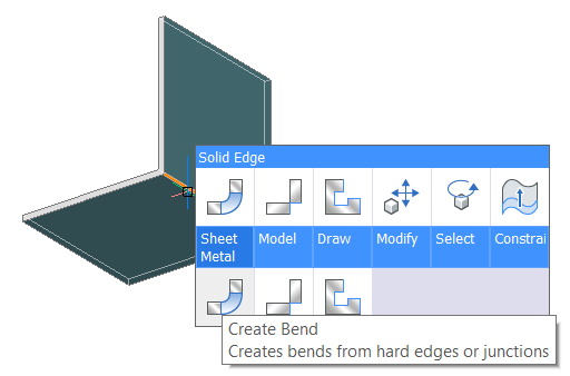
Najedź kursorem na twardą krawędź i kliknij narzędzie Utwórz zagięcie (
 ) w menu Quad .
 -
Kliknij przycisk narzędzia Utwórz skrzyżowanie (
) na karcie wstążki Arkusz Blachy . -
Wybierz Utwórz zagięcia w menu Arkusz Metalowy.
-
Wpisz ABGIĘCIE w wierszu polecenia.
Pojawi się monit:
Wybierz twarde krawędzie, połączenia, kołnierze lub bryły 3D lub [Cały model/opcje wyboru (?)] <Cały<Entire model> model>:
-
-
Wybrać ścianę kołnierza lub twardą krawędź.
Pojawi się monit:
Elementy w zestawie: 1
Wybrać powierzchnie kołnierza lub twarde krawędzie:
- Wykonaj jedną z następujących czynności:
- Wybierz więcej powierzchni lub twardych krawędzi.
- Kliknij prawym przyciskiem myszy lub naciśnij Wprowadź, aby utworzyć zagięcia lub połączenia na wybranych elementach.
 |
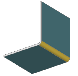 |
| Wybrano twardą krawędź | Powstaje gięcie |
Konwersja twardych krawędzi na złącza
- Wykonaj jedną z następujących czynności:
-
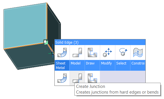
Najedź kursorem na twardą krawędź i kliknij narzędzie Utwórz skrzyżowania (
 ) w menu Quad .
 -
Kliknij przycisk narzędzia Utwórz skrzyżowanie (
) na karcie wstążki Arkusz Blachy . -
Wybierz opcję Utwórz połączeń w menu Arkusz Blachy.
-
Wpisz ABZŁĄCZE w wierszu polecenia.
Zostanie wyświetlony monit: Wybierz twarde krawędzie, zagięcia, kołnierze lub bryły 3D [Cały model/opcje wyboru (?)] <Cały<Entire model> model>:
-
-
Wybrać ścianę kołnierza lub twardą krawędź.
Pojawi się monit:
Elementy w zestawie: 1
Wybrać powierzchnie kołnierza lub twarde krawędzie:
- Wykonaj jedną z następujących czynności:
- Wybierz więcej powierzchni lub twardych krawędzi.
- Kliknij prawym przyciskiem myszy lub naciśnij Wprowadź, aby utworzyć zagięcia lub połączenia na wybranych elementach.
 |
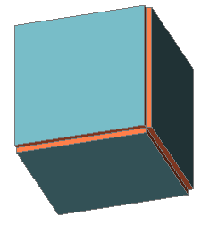 |
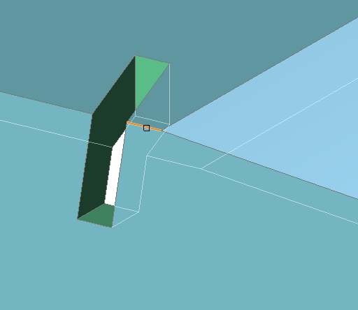
| Wybrane twarde krawędzie. Zauważ, że najpierw należy utworzyć wycięcie narożne. |
Utworzono złącza. Zwróć uwagę, że niepotrzebne cięcia materiału zostały usunięte ze względu na funkcji Smart Features. |
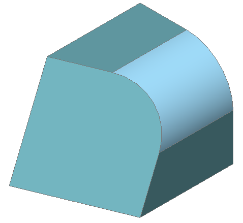
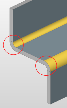
Tworzenie zakrzywionych złącz
-
Utworzyć wycięcie pod gięciem dla jednej z liniowych twardych krawędzi.
-
Wyciąć złącza dla pozostałych liniowych i zakrzywionych twardych krawędzi.
-
Utwórz zagięcie na pozostałej twardej krawędzi.
-
Tworzenie podcięć zgięć.
Wykonaj jedną z następujących czynności:
-
Kliknij przycisk narzędzia Utwórz podcięcia (
 ) na karcie wstążki Arkusz blachy .
 -
Wybierz Utwórz zagięcia w menu Arkusz metalowy.
-
Wpisz ABWYCIĘCIE w wierszu polecenia.
Pojawi się monit:
Wybierz twardą krawędź lub ścianę zgięcia, ścianę kołnierza, bryłę 3D [Cały model/opcje wyboru (?)] <Cały<Entire model> model>:
-
-
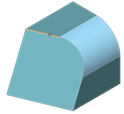
Wybierz twardą krawędź.
Pojawi się monit:
Podaj kolejną twardą krawędź lub powierzchnię gięcia dla wycięcia narożnego
-
Naciśnij Enter lub kliknij prawym przyciskiem myszy.
Pojawi się monit:
Podaj rozmiar wycięcia przez stosunek promienia gięcia lub [wymuś wycięcie gięć/Auto] <Auto>:
-
Naciśnij Enter lub kliknij prawym przyciskiem myszy.
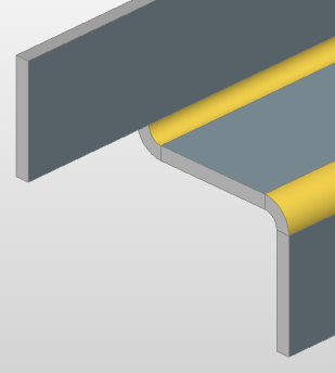
Dla krawędzi tworzone są 2 podcięcia na zgięcie:
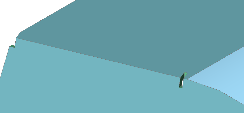
2 podcięcia zgięć są tworzone, ponieważ twarda krawędź z wierzchołkiem wolnym od wymaga podcięcia, aby utworzyć prostopadłą ścianę grubości.
Podcięcie zagięcia po stronie przylegającej do zgięcia wyciągniętego jest tworzone, ponieważ ta cecha różni się od zwykłego zagięcia: utworzenie podcięcia narożnika byłoby zbyt duże.
-
Utwórz 2 skrzyżowania.
Wykonaj jedną z następujących czynności:-
Kliknij przycisk narzędzia Utwórz skrzyżowanie (
) na karcie wstążki Arkusz Metalowy; -
Wybierz opcję Utwórz połączeń w menu Arkusz Blachy.
-
Wpisz ABZŁĄCZE w wierszu polecenia.
Pojawi się monit:
Wybierz twarde krawędzie, zgięcia, kołnierze lub bryły 3D [Cały model] <Cały<Entire model> model>:
-
-
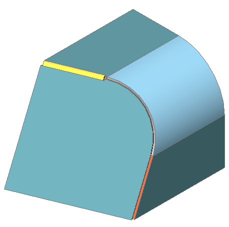
Wybierz następujące 3 twarde krawędzie:
Rozważ małą twardą krawędź:
Cięcie zostanie utworzone. Części odpowiadające krawędzi liniowej uzyskują cechy regularnego złącza.
-
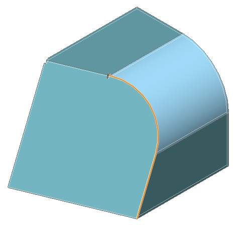
Utwórz zagięcie na twardej krawędzi. Ponieważ jest to jedyna twarda krawędź pozostała w modelu, zastosuj to polecenie do całego modelu.
-
Kliknij przycisk narzędzia Utwórz skrzyżowanie (
) na karcie wstążki Arkusz Blachy . -
Wybierz Utwórz zagięcia w menu Arkusz Metalowy.
-
Wpisz ABGIĘCIE w wierszu polecenia.
Pojawi się monit:
Wybierz twarde krawędzie, połączenia, kołnierze lub bryły 3D lub [Cały model] <Cały<Entire model> model>:
-
-
Naciśnij Enter.
Zagięcie zostanie utworzone.
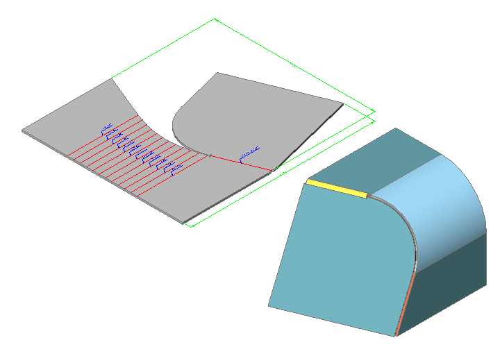
- Rozłóż część.
-
Kliknij przyciski narzędzia Rozwiń bryłę (
 ) na karcie wstążki Arkusz blachy .
 -
Wybierz Rozwiń bryły w menu Arkusz Blachy.
-
Wpisz ABROZWIŃ w wierszu polecenia.
Pojawi się monit:
Wybierz kołnierz lub wyciągniętą ścianę zgięcia, aby rozpocząć rozwijanie [Zespolone]:
-
-
Wybrać jakąś ścianę kołnierza.
Pojawi się monit:
Wybierz pozycję rozłożonego korpusu
-
Umieść rozłożoną część.
Pojawi się monit:
Zatwierdź rozwinięty obiekt i wybierz opcję [zapisz geometrię 2D/zapisz geometrię 3D/Optymalizuj opisy zgięcia/Zachowaj] <Keep>:
- Naciśnij Enter , aby zachować wynik.
Aby podzielić ścianę grubości
Aby wydłużyć kołnierz, który ma tę samą grubość ścianki, co inne kołnierze, ściana grubości musi zostać podzielona.
- Uruchom polecenie ABODCISK (
 ).
).Monituje: Wybierz ścianę grubości:
- Wybierz ścianę wspólnej grubości.
- Kliknij prawym przyciskiem myszy lub naciśnij Enter , aby podzielić powierzchnię.
- Kołnierze można teraz przedłużyć oddzielnie:
- Wykonaj polecenie MBUPROŚĆ, aby usunąć niepotrzebne podziały, ujednolicając w ten sposób współpłaszczyznowe ściany grubości.
Zmiana Promienia Gięcia
Aby zmienić całkowity promień gięcia:
- Wybierz węzeł główny w Przeglądarki Mechanical.
- Znajdź grupę Promień zgięcia w dolnej części Przeglądarka Mechanical.
- Wykonaj jedną z następujących czynności:
- Ustaw polu Typ Wartość bezwzględną, a następnie wpisz wartość promienia w polu Wartość .
Pole Promienia zgięcia zmienia się odpowiednio.
- Ustaw Typ na Współczynnik grubości, a następnie wpisz wartość w polu Współczynnika.
Pole Promień zgięcia jest obliczane jako iloczyn Grubości i Współczynnika grubości.
- Ustaw polu Typ Wartość bezwzględną, a następnie wpisz wartość promienia w polu Wartość .
Aby zmienić promień gięcia dla konkretnego gięcia:
- Wybierz węzeł zgięcia w Przeglądarka Mechanical. Wybrane zgięcie zostanie podświetlone w modelu. Właściwości zgięcia wyświetlane w dolnej części Przeglądarki Mechanical.
- Wykonaj jedną z następujących czynności:
- Ustaw Typ na Użyj wartości globalnej.
Bieżący globalny promień gięcia jest zastosowany do wybranego gięcia.
- Ustaw Typ na Wartość bezwzględna, a następnie wpisz wartość promienia w polu Wartość.
Pole Promienia zmienia się odpowiednio.
- Ustaw Typ na Współczynnik grubości i wpisz wartość w polu Współczynnik.
Pole Promień zgięcia jest obliczane jako iloczyn Grubości i Współczynnika grubości.
- Ustaw Typ na Użyj wartości globalnej.
Zmiana Szczeliny Złącza
Aby zmienić ogólną szczelinę złącza:
- Wybierz węzeł główny w Przeglądarki Mechanical.
- Zlokalizuj grupę Szczelina między złączami w dolnej części Przeglądarki Mechanical.
- Wykonaj jedną z następujących czynności:
-
Ustaw polu Typ Wartość bezwzględną, a następnie wpisz wartość promienia w polu Wartość .
Pole Szczelina złącza odpowiednio się zmieni.
-
Ustaw Typ na Współczynnik grubości, a następnie wpisz wartość w polu Współczynnika.
Pole Szczelina między złączami jest obliczane jako iloczyn Grubości i Współczynnika grubości.
-
Aby zmienić szczelinę złącza dla konkretnego gięcia:
- Wybierz węzeł zgięcia w Przeglądarka Mechanical. Wybrane zgięcie zostanie podświetlone w modelu. Właściwości zgięcia wyświetlane w dolnej części Przeglądarki Mechanical.
- Wykonaj jedną z następujących czynności:
-
Ustaw Typ na Użyj wartości globalnej.
Bieżąca globalna przerwa między złączami jest stosowana do wybranego skrzyżowania.
-
Ustaw Type na Wartość bezwzględna, a następnie wpisz wartość odstępu w polu Value .
Pole Szczelina złącza odpowiednio się zmieni.
-
Ustaw Typ na Współczynnik grubości i wpisz wartość w polu Współczynnik.
Pole Szczelina między złączami jest obliczane jako iloczyn Grubości i Współczynnika grubości.
-
Zmiana Typu Złącza
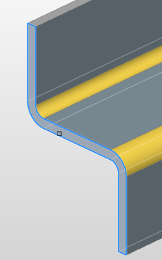
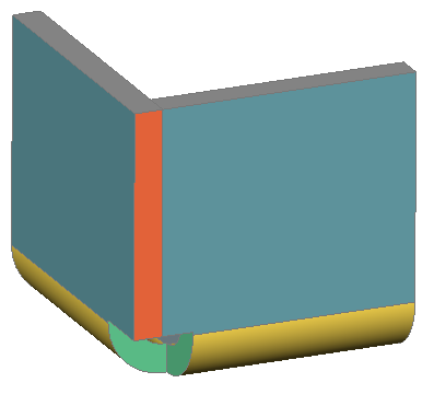
Domyślnie BricsCAD® tworzy skrzyżowania symetryczne, jak pokazano na poniższym obrazku:
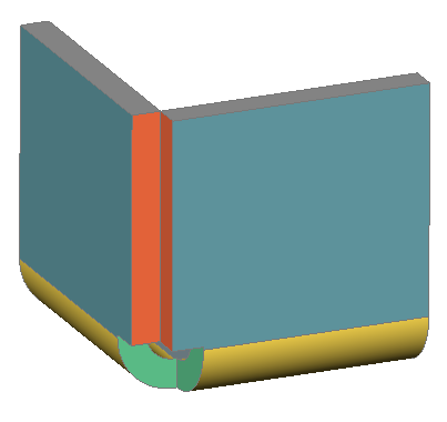
Polecenie ABPRZEŁĄCZZŁĄCZE umożliwia zmianę elementu połączenia symetrycznego na element z nakładającymi się powierzchniami.
Aby zmienić typ skrzyżowania za pomocą menu Quad:
- Ustaw kursor nad jedną ze ścian grubości tego złącza.
- Wybierz Typ skrzyżowania przełącznika w grupie poleceń Arkusz blachy w menu Quad .
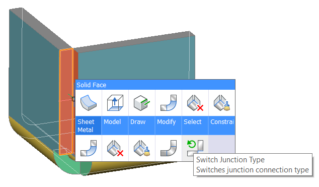
Wybrana ściana grubości jest wyrównana ze ścianą kołnierza.
Aby zmienić typ złącza w Przeglądarce Mechanical:
Metoda 1:
-
Wybierz odpowiednie skrzyżowanie w drzewie.
Właściwości złącza są wyświetlane w dolnej części Przeglądarki Mechanical.
-
Wybierz właściwość Typ połączenia.
-
Wybierz żądany typ skrzyżowania.
Dostępne opcje to: Symetryczny, Wyrównany do Flange_X lub Wyrównany do Flange_Y.
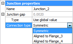
Skrzyżowanie zostanie odpowiednio zaktualizowane.
Metoda 2:
-
Wybierz odpowiednie skrzyżowanie w drzewie.
Zostanie wyświetlone menu kontekstowe:
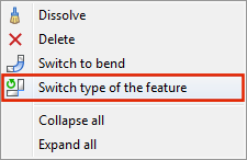
- Kliknij prawym przyciskiem myszy i wybierz Przełącz typ funkcji z menu kontekstowego.