Working with Bevels
Overview
Bevel features represent a chamfer operation made on Sheet Metal parts. On the level of BricsCAD V21 each bevel should be exactly on a single flange. There are no specific operations to create a bevel, so the DMCHAMFER command must be used on an edge of a flange, and then use DMROTATE to adjust the bevel angle. The SMCONVERT command recognizes the bevels and is processed by SMUNFOLD. Bevel features are also supported by the SMDELETE and SMREPAIR commands.
- Working with importing geometry, including batch export by SMASSEMBLYEXPORT.
- Modifying parts.
We distinguish between the following bevel types:
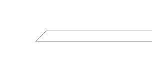 |
One-side bevel |
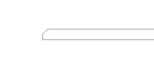 |
Land bevel |
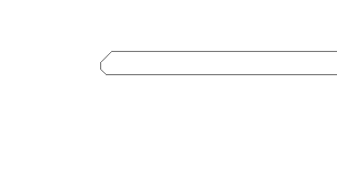 |
K-bevel |
 |
X-bevel |
In the Mechanical Browser, the properties of each chamfer of a bevel feature are available separately. These properties are:
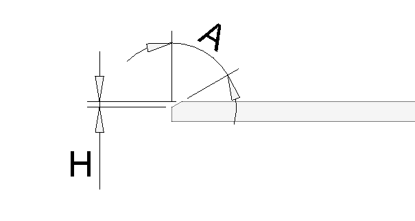
Depth (H): the depth of the chamfer operation, much like the DMCHAMFER command does.
Angle (A): the slope of the chamfered face.
Recognizing bevels
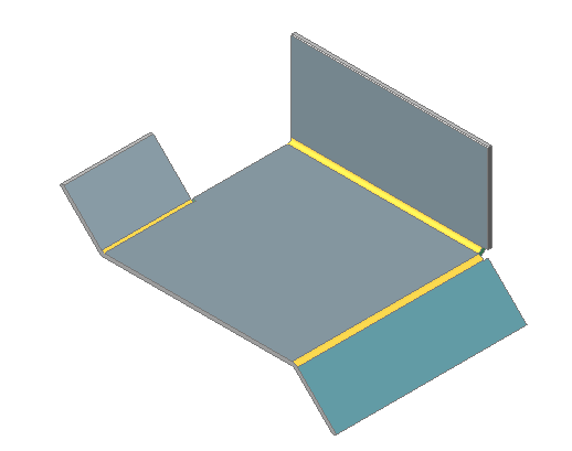
Let us start with a sheet metal part with bevel geometry (chamfered flange edges).
- Click the Convert to Sheet Metal (
 ) tool button on the Sheet Metal / Create Ribbon panel.You are prompted: Select 3D solids or seed faces or [Entire model/selection options (?)] <Entire model>:
 - Press Enter to convert the 3D solid to a sheet metal part.
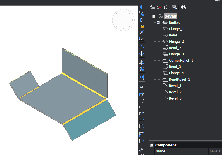
The bevel features are recognized and appear in Mechanical Browser and show on the part:
Delete and Repair
The following round trip does not change the overall dimensions of the part: Create the bevel geometry and feature using DMCHAMFER/SMCONVERT, then delete the bevel using SMDELETE and restart the procedure.
When using SMDELETE to delete a bevel the volume is always added to the part because the dimensions of the part can not be reduced.
Support in the SMREPAIR command is also important, since this command is a part of the Import and Rework workflow.
Unfold
Bevel features are unfolded according to the Unfolding Mode setting in the Mechanical Browser.
The options are:
Keep: Does nothing with bevel geometry, resulting in a 3D solid with chamfers. These chamfered faces will likely produce artifacts in the 2D .DXF.
Remove: Same result as applying SMDELETE on all the bevel features: all the chops are filled.
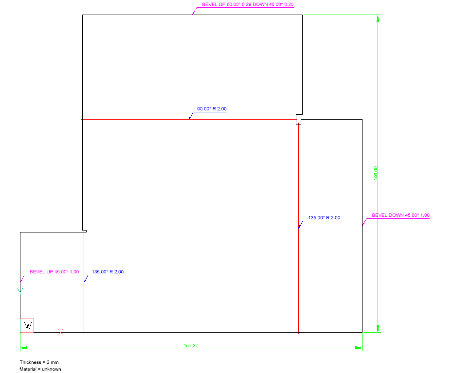
Annotate: Each bevel feature is removed and the edge is annotated. This mode is recommended.
- Each bevel edge has been annotated with a pink text on the Bevel Annotations layer.
- UP and DOWN are with respect to the selected side for unfolding. When choosing the opposite side, all the UP annotations become DOWN, and vice versa.
- For One-side and Land bevels a single chamfer operation is needed only: a single UP or Down annotation is created.
- For K- and X- bevels 2 chamfer operations are needed: UP and DOWN annotations are created.