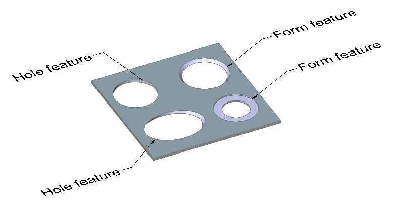
Las características de los agujeros son una versión simplificada de Características de la forma. En la siguiente imagen puede ver diferentes entidades, que solo tienen caras de espesor (el comando SMCONVERT respeta estas reglas):
Los agujeros ortogonales son características de los agujeros.
Los agujeros simples no ortogonales son características de los agujeros.
Los agujeros ortogonales cortafuegos son características de forma.
Si la cara de espesor del hoyo consta de 2 regiones diferentes, es una característica de forma.
Las características de los agujeros son reconocidas por el comando SMCONVERT si la preferencia del usuario SMCONVERTRECOGNIZEHOLES está activada.
Se permiten las siguientes operaciones básicas para las entidades de agujeros:
SMDELETE, SMDISSOLVE, desactivar y SMSELECT mediante comandos o en el Browser Mecánico para Chapa.
Modos de entidad de formulario en el comando SMUNFOLD, incluido el modo Símbolo.
Asocie su propia geometría 2D en un diseño aplanado.
Las entidades de agujeros se conservan mediante el comando SMREPAIR. Las caras de los agujeros se vuelven ortogonales. Un elemento de orificio de la misma geometría no se ve afectado por el comando SMREPAIR.
Reconocimiento de conjuntos de rasgos de agujeros
Cuando existen características de agujeros en un cuerpo, el comando SMPARAMETRIZE detecta matrices rectangulares de agujeros en las bridas, de acuerdo con las siguientes reglas:
Los agujeros pertenecen a la misma brida.
Los agujeros están en una cuadrícula rectangular.
No hay lagunas (elementos faltantes) en la matriz.
Agujeros están orientados por igual.
El tamaño mínimo de la matriz es 1x3 o 2x2.
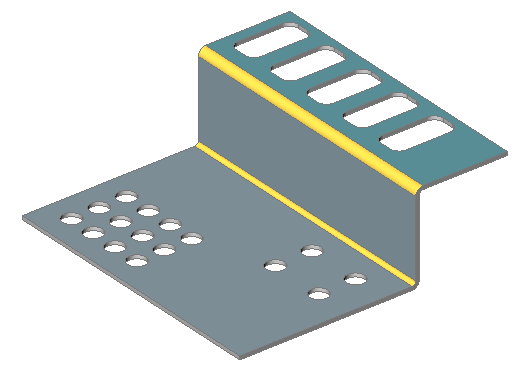
Vamos a ilustrar el flujo de trabajo de una parte con las características de Brida y Curva.
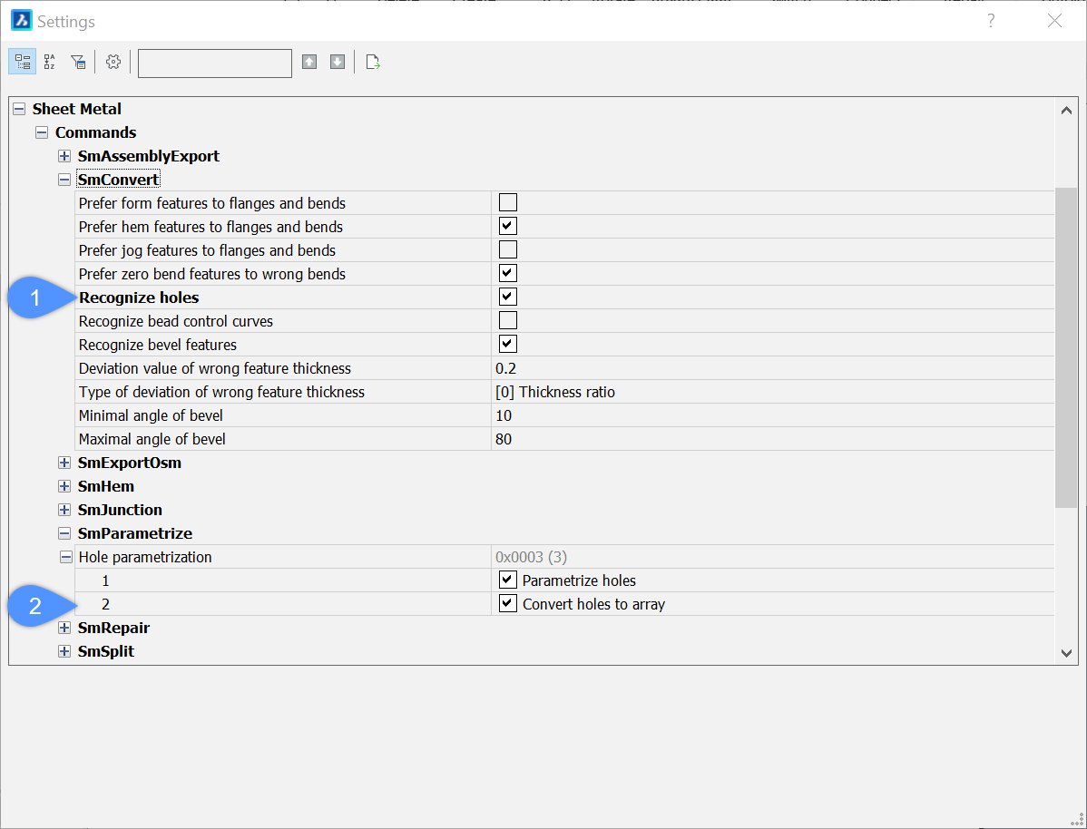
En el cuadro de diálogo Configuración, vaya a Chapa metálica/Comandos.
Habilite la opción Reconocer agujeros (1) para el comando
SMCONVERT .
Habilite las opciones Convertir agujeros en matriz (2) y Parametrizar
agujeros para el comando SMPARAMETRIZE .
Ejecute el comando SMCONVERT.
Haz una de las siguientes cosas:
Haga clic en el botón de herramienta Convertir a chapa metálica () en la barra de herramientas Chapa metálica .
Haga clic en el botón de herramienta Convertir a chapa metálica () en la barra de la cinta Chapa metálica .
Elija Reparar chapa metálica en el menú Chapa metálica.
Se le solicitará: Seleccione Sólidos 3D o [Modelo completo] <Modelo completo>:
Seleccione el sólido 3D para convertir.
Se le solicitará: Seleccione Sólidos 3D o [Modelo completo] <Modelo completo>:
Pulse Enter para convertir el sólido 3D en una pieza de metal.
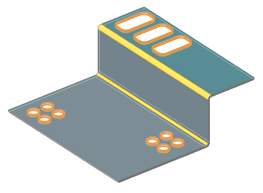
Se reconocen 11 características de agujeros en la pieza.
Ejecute el comando SMPARAMETRIZE.
Haz una de las siguientes cosas:
Haga clic en el botón de la herramienta Parametrizar () en la barra de herramientas Chapa metálica .
Haga clic en el botón de la herramienta Parametrizar () en la barra de la cinta Chapa metálica .
Elija Parametrizar en el menú Chapa metálica .
Se le solicitará: Seleccione sólidos 3D para parametrizar o [Modelo completo] <Modelo completo>:
Presione Enter para crear la pieza de chapa metálica.
Los informes de comando deben verse como el siguiente:
Creó 4 restricciones de distancia
Creó 3 restricciones de corrección
Creó 0 restricciones coincidentes
Creó 0 restricciones tangentes
Creó 0 restricciones de conjunto rígido
Se creó una matriz rectangular 2x2 basada en la característica Hole_3
Se creó una matriz rectangular 2x2 basada en la característica Hole_7
Se creó una matriz rectangular 3x1 basada en la característica Hole_9
Total: 7 restricciones y 3 matrices creadas
Note: Los nombres de características y la distribución de restricciones pueden diferir dependiendo de la versión de BricsCAD.
Para examinar las matrices, puede descongelar temporalmente la capa BC_SUBTRACT .
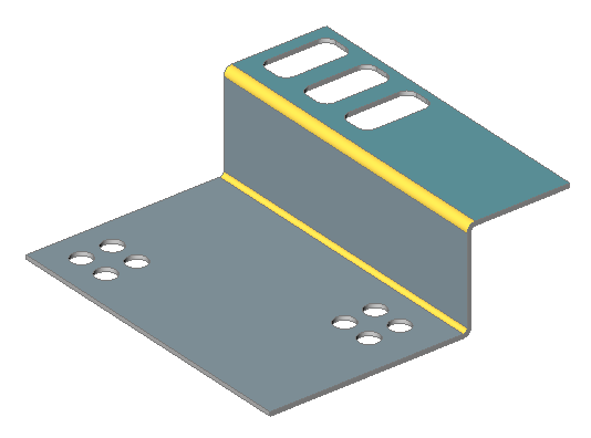
En la imagen de abajo, las matrices están coloreadas manualmente.
Note: Los arreglos verde y amarillo no están unificados. De lo contrario, el conjunto tendría agujeros perdidos.
Edite las Propiedades de matriz en el Navegador mecánico.
En la imagen de abajo se ha modificado lo siguiente:
Matriz verde: número de filas y columnas de 2x2 a 3x4.
Arreglo amarillo: espaciado X e Y.
Matriz roja: número de filas y columnas de 3x1 a 5x1.


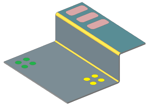 Note: Los arreglos verde y amarillo no están unificados. De lo contrario, el conjunto tendría agujeros perdidos.