


Basic concepts of modeling in BricsCAD Shape
Selection methods
Highlighting and selecting objects
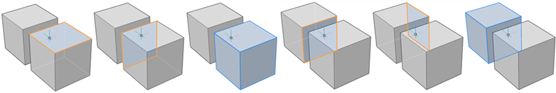
Entities in BricsCAD Shape are solids, which are made up of edges and faces.
When hovering over an entity, a part of the entity is highlighted. To select the highlighted part of the entity, left-click the edge or face.
For some operations, it’s not necessary to select entities. When a surface or edge is highlighted, the Quad opens and several commands can be accessed.
Sometimes, the entity you want to select is hidden behind other entities. Place the cursor over the obscured entity, then repeatedly press the TAB key. All (sub)entities under the cursor highlight one by one. Click to select the currently highlighted (sub)entity.
To clear a selection of objects, press the ESC button.
Selection windows
To select one or multiple elements at once, a selection window is used. Left click on an empty space in the model area. When you move the cursor a selection window displays.
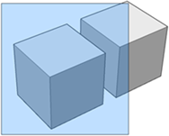
Blue selection window
Moving the cursor from left to right, a blue selection window displays: all entities that are completely inside the rectangle are selected. This selection method is called ‘Window Inside‘.
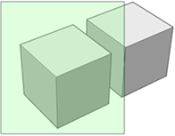
Green selection window
Moving the cursor from right to left, a green selection window displays: all entities that are completely inside or overlapping the selection rectangle are selected. This selection method is called ‘Window Overlap’.
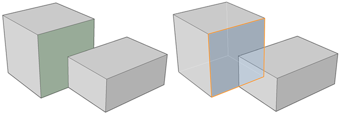
Boundaries vs Faces
Boundaries can be defined by a set of 2D entities in the XY field of the current coordinate system or on a 3D solid face or by partially overlapping faces of 3D solids. BricsCAD Shape automatically detects and highlights closed boundaries, as you hover over different model elements. When a boundary is detected, it will be highlighted. To select it, just left-click inside the highlighted boundary. Boundaries can be used to create new solids or making holes or offsets and recesses.
Quad
The Quad cursor menu, or Quad for short, is an alternative to the Command line, toolbars or ribbon, offering a rich set of tools while requiring fewer clicks, without cluttering the screen with loads of grip-glyphs. It includes rollover tips, which display a limited set of properties when selecting or hovering over an entity.
The Quad displays when:
- You hover over an entity.
- A selection set exists.
- You right click on an empty space on the screen. This will open the No Selection Quad.
The initial content of the Quad when hovering over an entity is:
- Entity type.
- The icon of the most recently used command on this entity type.
- Relevant properties.
When you move the cursor to the Quad, it expands. On top you can find the most relevant or most recently used commands for the entity. Below you see a series of command tabs:
- Move the cursor over a tab to expand it.
- Place the cursor over an item to see a tool tip.
- Click an icon to launch a command.
- Click the Quad title bar to collapse, click again to expand.
Manipulator
The manipulator allows you to move, rotate scale and mirror selected entities and optionally create copies.
To display the Manipulator do one of the following:
- Select the entity or subentity and choose Manipulator in the Modify tab on the Quad.
- Hold down the left mouse button a little bit longer when selecting.
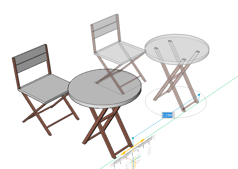
Select an axis
By selecting an axis of the manipulator you are able to move the entity. Specify the value of displacement by entering a value or picking a point. The step size of the ruler depends on the zoom factor. Zoom in to decrease the step size, zoom out to increase.
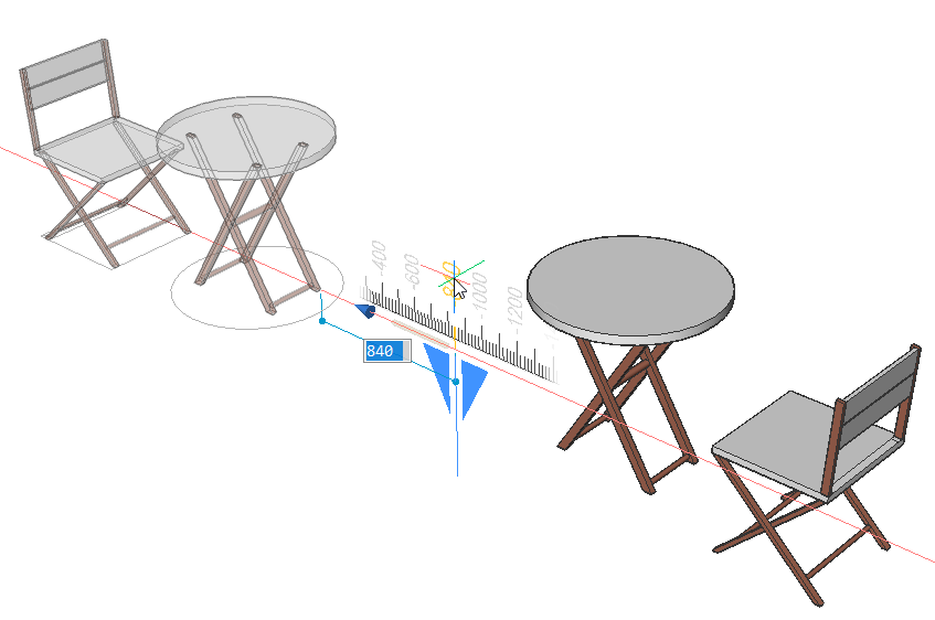
Select a plane
By selecting a plane of the manipulator you are able to move the entity in the selected plane after specifying the value of displacement by entering a value or picking a point.
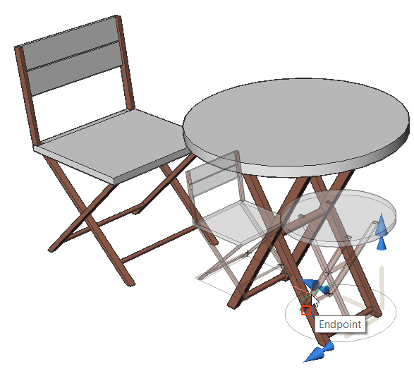
Select an arrowhead
By selecting an arrowhead of the manipulator you are able to scale or rotate the selected entity. By right clicking when hovering over the entity, a contexts menu with other options is displayed. There the function of an arrowhead can be changed between 3D mirror and 3D scale.
Select one of the arrowheads and specify the mirror axis or scale.
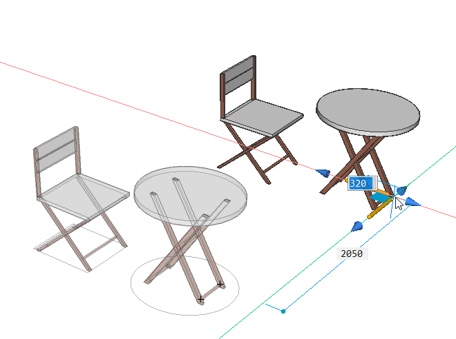
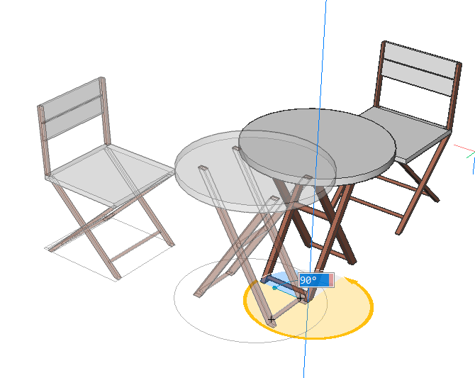
Select a rotation arc
By selecting an arc of the manipulator you are able to rotate the entity after entering the rotation angle value or specifying by clicking on a point in the drawing.
Select the anchor handle
By selecting the anchor of the manipulator you are able to relocate the manipulator.