The Offset tool allows you to create copies of linear entities and align them parallel to the original entities at a specified distance.
Depending on the selected options in the Selection Modes toolbar, the Offset tool allows you to create a parallel copy of:
An edge of a 3D solid if the Select Edges option () is enabled or if the SELECTIONMODES system variable is set to 1.
The edges of a 3D solid face if the Select Faces option () is enabled or if the SELECTIONMODES system variable is set to 2.
Detected boundaries if the Select Detected Boundaries option () is enabled or if the SELECTIONMODES system variable is set to 4.
Procedure: make a parallel copy of a 3D solid edge
Before starting the process, make sure that Quad is active and the Select Edges option in the Selection Modes toolbar is on. Next, follow these steps:
Move the cursor over the edge of the solid to highlight the edge.
Choose the Offset tool from the Quad.
Specify the offset distance by dragging the edge of the solid face.
Note: The distance of the offset displays in the dynamic dimension field. The parallel copy of the edge is created dynamically.
While dragging the edge to set a precise offset distance, type a distance in the dynamic entry field and press Enter or left-click to accept the offset.
The following illustration shows the offset edge on the 3D solid. The edge highlights in orange is the original edge (1) of the 3D solid, whereas the blue highlighted line with grips (2) is the offset copy of the original one. The line (3) between the original edge and copied edge gives the offset distance.
Procedure: Make a parallel copy of a 3D solid face
Before starting the process, make sure that Quad is active and the Select Faces option in the Selection Modes toolbar is on. Next, follow these steps:
Move the cursor over the face of the solid to highlight the solid face.
Choose the Offset tool from the Quad.
Specify the offset distance by moving the cursor outside or inside of the solid.
The parallel copy of the face is created dynamically.
Enter a distance in the dynamic entry field and press Enter, or left-click to finish the offset.
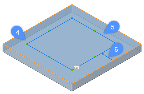
The following illustration shows the offset of the 3D solid face. The highlighted face is the original 3D solid face (4), whereas the created polyline (5) is the offset from the original one. The line (6) between the original 3D solid face and copied polyline gives the offset distance.
Procedure: make a parallel copy of a detected boundary
Before starting the process, make sure that Quad is active and the Select Detected Boundaries option in the Selection Modes toolbar is on. Next, follow these steps:
Move the cursor inside the boundary to highlight the detected boundary.
Choose the Offset tool from the Quad.
Move the cursor to define the offset distance and left-click.
The parallel copy of a detected boundary is created dynamically.
Enter a distance in the dynamic entry field to set a precise offset distance and press Enter or left-click to accept the offset.
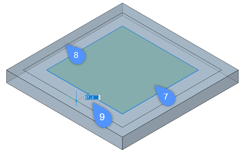
The following illustration shows the offset boundary on the face of a 3D solid. The highlighted face is the detected boundary (7), whereas the created polyline (8) is the copy from the original one. The line (9) between the detected boundary and copied polyline gives the offset distance.


 ) is enabled or if the SELECTIONMODES system variable is set to 1.
 ) is enabled or if the SELECTIONMODES system variable is set to 2.
 ) is enabled or if the SELECTIONMODES system variable is set to 4.