
Associative Unfolded Representations of 3D Solids
About
BricsCAD offers bidirectional associativity between the 3D sheet metal entities and their flattened representations. In this mode, each version is stored in a separate document: the Original part in its native document and the Flattened part in a temporary document.
Associativity remains active only while both documents are open. To use associativity in a new BricsCAD session or after closing the documents, you must repeat the setup steps.
What does associativity mean?
Associatively unfolding sheet metal entities allows you to modify the flattened geometry and propagate the changes to the 3D model.
There are two main purposes of associatively unfolding sheet metal entities:
- Creating complex, non-standard bends and corner relief cuts.
- Avoiding self-intersections in unfolding.
Associativity is bidirectional, allowing changes to be transferred between flattened entities and 3D models. Updates in one representation are applied to others when they become active.
Unfolding a sheet metal body
The associativity mode is turned on using the SMUNFOLD command.
From the Sheet Metal section of the Ribbon, select the Associatively Unfold Body icon ( ) and select Flange face.
The application will flatten the selected entity and switch to associative mode. The operation is successful if it meets the same criteria as regular unfolding. You can continue in associative mode only if no errors or warnings occur.
A temporary document with the flattened entity is created.
- There is no need to save this document. It is used to propagate editing operations from the flattened entity back to the 3D model.
- In the Mechanical Browser, when the flattened geometry is selected, it lists features that are disabled.
 ) on the Toolbar or Ribbon to tile the opened documents vertically and zoom to the collision area.
Editing the geometry
Associatively unfolding sheet metal entities allows users to easily create or modify custom features.
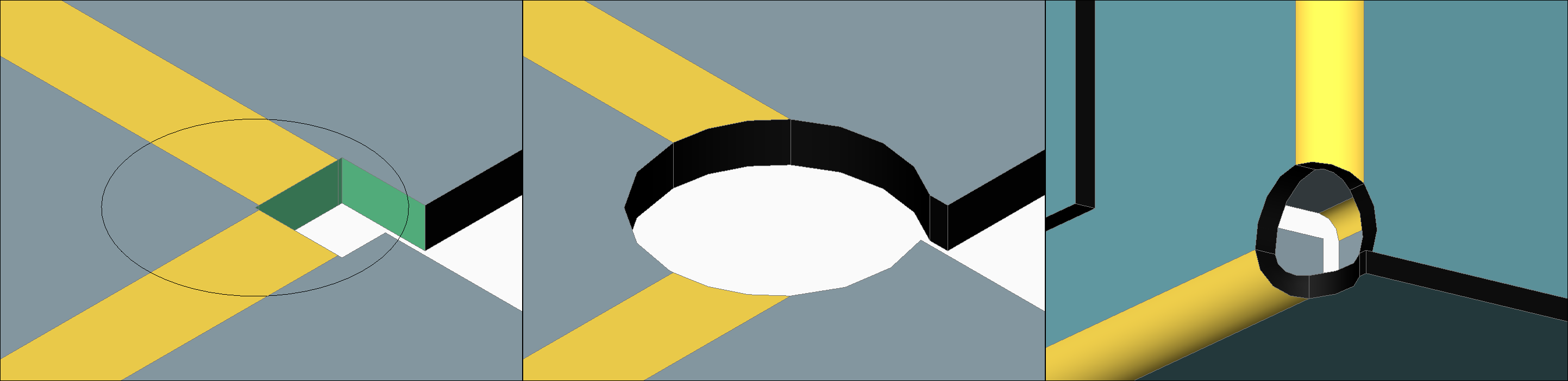
You can add a custom corner relief to a sheet metal entity by editing its unfolded version:
- In the flattened design document, draw a circle in the corner.
- Apply DMEXTRUDE command to the circle and subtract the volume.
- Click on the original document again to make it active.
- The model is updated and the custom corner relief appears.
The Command line displays the message: Changes were successfully transferred to source model.
Avoiding collisions in flat pattern
Geometry collisions in unfolded sheet metal entities can be fixed by modifying the flattened geometry using associative unfolding.
- From the Sheet Metal section of the Ribbon, select the Associatively Unfold Body icon () and select a Flange face to unfold the selected body.Tip: Use Vertical Tile to view both the 3D model and associative unfolding documents.
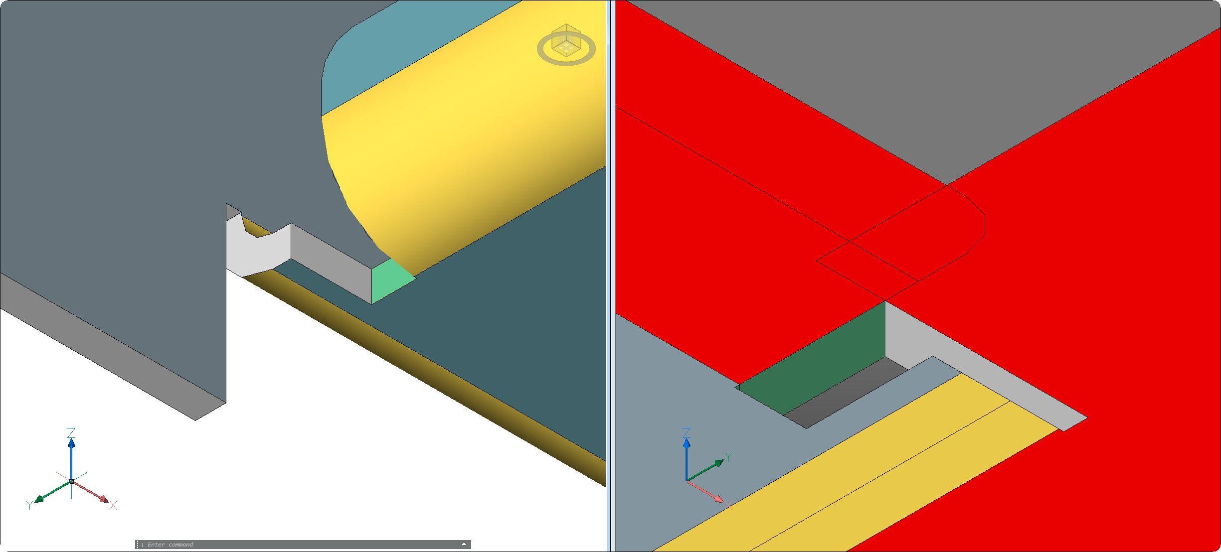
- In the unfolded drawing, draw a polyline on the edge of the collision.
- DMEXTRUDE the polyline and DMTHICKEN the newly created surface.
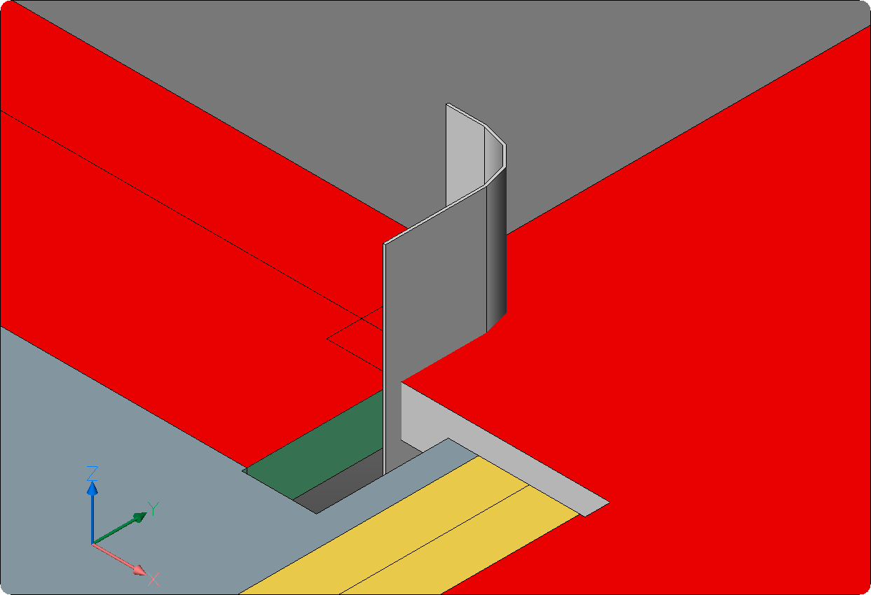
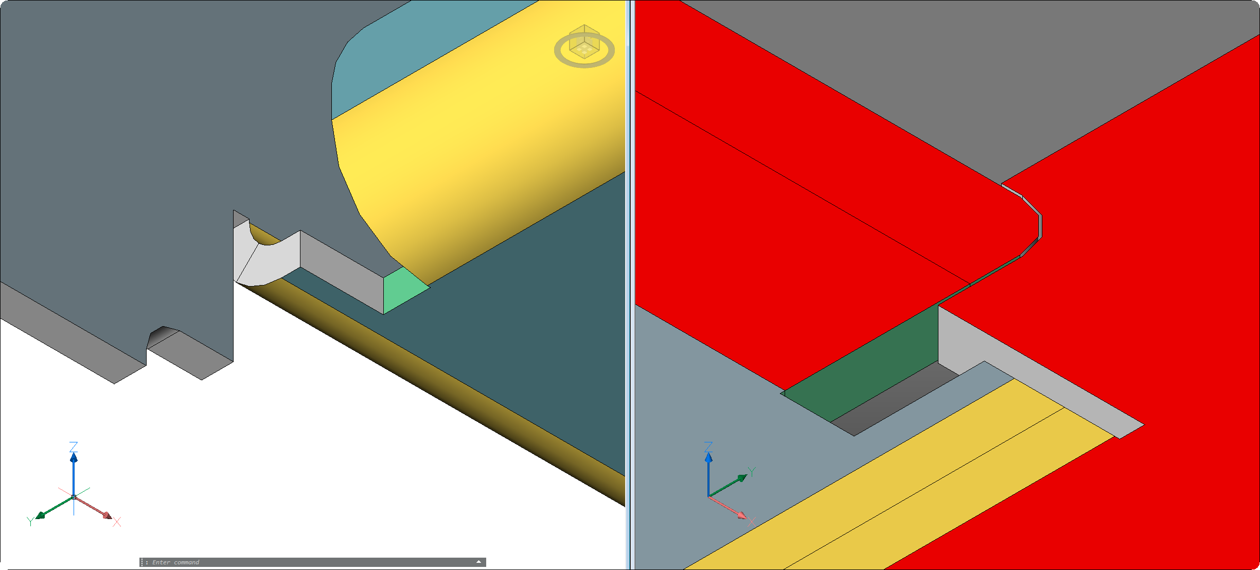
- SUBTRACT the thickened body from the unfolded sheet metal entity.
- ERASE the leftover pieces.
- Click on the original document again to make it active.
- The collision resolved in the flattened geometry is propagated to the original sheet metal entity.
- (Optional) Export the file as DXF to test the 2D unfold.