Sheet Metal Features
Overview
Features are smart groups of faces in a 3D part. Each feature maintains a specific spatial and parametric relationship between its faces and some adjacent faces. The features allow you to embed design intent into your model. The features are created automatically by a particular geometric operation you apply. Images below show the sheet metal features in BricsCAD®:
Example 1 of sheet metal features
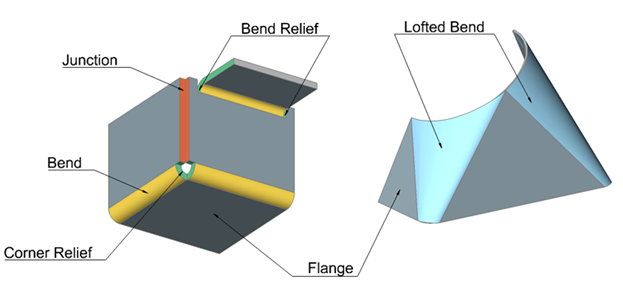
Example 2 of sheet metal features
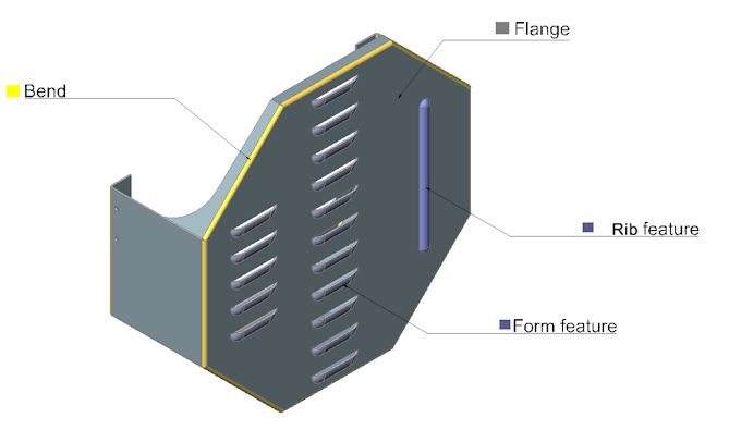

 Flange
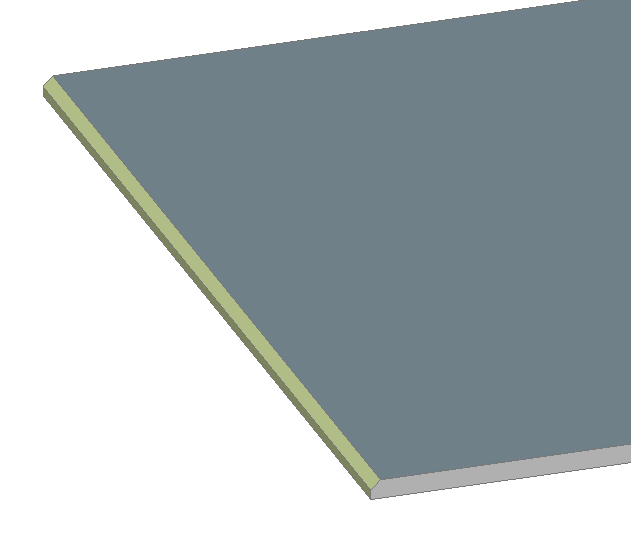
The main feature of all sheet metal parts is a flange, which consists of 2 parallel planar faces located in front of each other (with some solid volume between them) on the distance, which is significantly smaller than the linear size of the faces. This distance is equal to the material thickness. When you modify the model, this distance relation is always maintained automatically. Other faces, which are adjacent to flange faces and do not belong to bends are called thickness faces. They are always perpendicular to the flange faces.
Flange features are created by the following commands: SMFLANGEBASE, SMEXTRUDE, SMLOFT, SMFLANGEEDGE, SMFLANGEBEND and SMCONVERT.
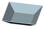
If the FEATURECOLORS system variable is ON, the display color distinguishes between the reference face of a flange and its opposite side. Parametric modifications of a sheet metal part, such as thickness change, do not move reference faces, if possible. The SMFLIP command swaps sides of a selected flange so that reference faces are on the other geometric side of the flange; optionally the command shifts the flange over the thickness of the sheet metal part.
The images below illustrate the color legend for the flange faces of the same part.
 |
 |
 Reference Faces Reference Faces |
 Other Faces Other Faces |
 Bend
Bend
Two flanges are connected by a bend. A bend consists of 2 coaxial cylindrical faces, which are always tangent to the adjacent planar faces of the flanges.
Bend features are created by SMFLANGEBASE, SMEXTRUDE, SMFLANGEEDGE, SMFLANGEBEND and SMCONVERT commands.
 Zero Bend
This is a design concept of bend, but geometry has a cylindrical face for the external side of the bend with a radius equal to thickness. Instead of an internal face, there is an edge. So effectively geometry represents a bend of zero radii, which is used for design purposes. SMUNFOLD operation supports bends of this kind and generates dimensions as if these bends were regular bends with a radius equal to thickness.
 Wrong Bend
Wrong bend features are recognized by the SMCONVERT command and reflect assumptions on the user’s design intent. Like regular bends, wrong bends connect flanges, but their faces can be non-coaxial, or they can have non-tangent connections with adjacent flange faces, which prevent using the geometry as regular bend features. Before unfolding the part, all wrong bends must either be repaired by SMREPAIR or removed by SMDELETE and then recreated by SMBENDCREATE.
 Lofted Bend
A lofted bend feature consists of 2 ruled surfaces located in front of each other (on the offset equal to the material thickness) with some solid volume between them. A ruled surface can be described as the set of points swept by a moving straight line. Examples are cylinders, cones, helicoids. Lofted bends can be created by the thickening of ruled surfaces. A lofted bend can connect 1 or 2 flanges or be stand-alone, without flanges at all. Some combinations of adjacency between regular bends and lofted bends are also allowed.
Differences between bends and lofted bends:
| Bends | Lofted Bends | |
|---|---|---|
| Surface | Cylindrical | Cylindrical, conical or spline |
| Unfolding | Exactly | The approximate unfolding of lofted bends is controlled by an adjustable number of bend operations, which are called the Number of Subdivisions. The more operations are performed, the smoother the real part will be produced and the better it approximates the initial design. Cylindrical and conical lofted bends have an option for exact analytical unfolding. |
Lofted bend features are created by the SMLOFT and SMCONVERT commands.
 Bend Relief
A group of faces representing a technological cut between 2 flanges of different width connected with a bend. The bend relief feature maintains the distance between 2 opposite faces of the cut.
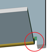
Bend relief features are created by SMFLANGEEDGE, SMBENDCREATE and SMRELIEFCREATE commands.
 Corner Relief
A group of faces representing a cut in the corner where 3 or more flanges meet together. This cut is needed to prevent unwanted material deformation during bending of the sheet metal part. A corner relief feature maintains the form and size of this cut.

Corner relief features are created by SMFLANGEEDGE, SMBENDCREATE and SMRELIEFCREATE commands.
 Junction and T-junction
A junction feature consists of 2 thickness faces of adjacent flanges, which are not connected by a bend. A junction can be symmetric or overlapping. Junction features maintain the minimal distance between the flanges: the junction gap.
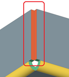
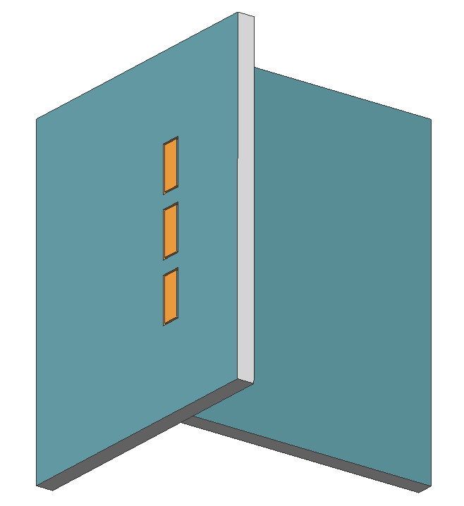
A T-junction feature consists of a thickness face of a single flange, which is located near a face of another flange,. Usually, a T-junction precedes creation of a T-tab.
For clarity, the junction gap in the image below is intentionally rather large.
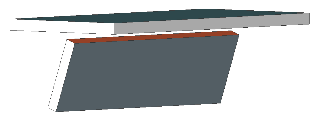
Junction features are created by SMFLANGEEDGE, SMJUNCTIONCREATE and SMFLANGECONNECT commands.
T-junction features are created by SMJUNCTIONCREATE and SMFLANGECONNECT commands.
 Miter Feature
A miter feature represents a split between coplanar flanges created by the SMFLANGEEDGE and SMSPLIT commands. A miter feature maintains the miter gap.

 Form and Rib Features
Form and rib features represent a rich variety of shapes which are produced by punching and wheeling.
Two representations of the form features are important: one in 3D and a 2D symbol in the unfolded geometry. In case of imported geometry the symbol is obtained by the projection of the 3D faces of the form feature. In case the form feature was inserted/replaced from the Form Feature Library, the unfolding symbol is taken from the library file.
Rib features represent the imprint on a flange made by a wheel following an arbitrary trajectory.
Form and rib features are created by BMINSERT, SMBEAD and SMCONVERT commands.
Tab and T-tab
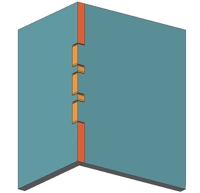
Both features are used to connect 2 flanges, restricting their mutual displacement.
Tab and T-tab features are created by the SMTABCREATE command.
|
|
| Tab feature | T-tab feature |
 Bevel
Bevel
Bevel features represent chamfers on thickness faces of Sheet Metal parts. Both sloped and orthogonal faces define a chamfer feature. Bevel features must be shared strictly by a single flange and can not be adjacent to bend features.
Bevel features can be recognized or erased by the SMCONVERT command, and are supported by the SMUNFOLD command.
