Creating multileaders
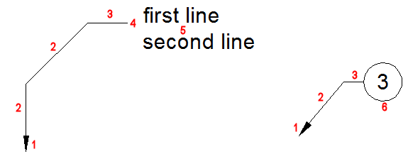
A multileader consists of:
- an arrowhead (1)
- one or more leader lines (2), which can be straight or curved
- optionally a horizontal landing (3) and landing gap (4)
- content: either a multiline text (5) or a block (6)

Multileaders are created using the current multileader style. Each drawing contains a Default leader style, which cannot be renamed or deleted; the Default leader style can be customized though. The MLEADER command allows to define overrides on the current multileader style.
Multileaders can be created arrowhead first, landing first or content first.

To create a multileader
- (option) Launch the MLEADERSTYLE command, then set the current multileader style.
- Do one of the following:
- Click the Multileader tool button (
 ) on the Dimensions toolbar or ribbon panel.
 - Choose Multileader in the Dimensions menu.
- Launch the MLEADER command.
You are prompted: Specify leader arrowhead location or [leader Landing first/Content first/Options] <Options>:
- Click the Multileader tool button (
- (option) Select a placement option:
- arrowhead first
- landing first
- content first.
The most recently used placement option is repeated.
- The default sequence is: arrowhead - landing - content.
- (option) Choose Options if you want to define overrides on the current multileader style.
You are prompted: Enter an option [Leader type/leader lAnding/Content type/Maxpoints/First angle/Second angle/eXit options] <eXit options>:
Specify the option(s), then choose Exit to proceed.
- Specify a point to define the leader arrowhead location.
You are prompted: Specify leader landing location:
- Specify a point to define the leader landing location.
- Depending on the content type:
- MText: The MText command is launched.
- Block: A block is inserted.
- None: The command is concluded.
Adding vertices to a leader line
- If necessary press the F12 function key to activate the Quad cursor menu.
- Pause the cursor over the leader line you want to add a vertex to, then hold down the Ctrl key.
The Quad cursor menu is displayed.
- Move the cursor to the Quad cursor menu and expand the Modify tab.
- Click the Add Vertex tool (
 ).
).A new vertex is added dynamically.
- Specify the position of the vertex.
Removing vertices from a leader line
- If necessary press the F12 function key to activate the Quad cursor menu.
- Pause the cursor over the leader line you want to add a vertex to, then hold down the Ctrl key.
The Quad cursor menu is displayed.
- Move the cursor to the Quad cursor menu expand the Modify tab.
- Click the Remove Vertex tool (
 ).
).The vertex is removed.
Adding leader lines to a multileader
- If necessary press the F12 function key to activate the Quad cursor menu.
- Pause the cursor over the multileader entity.
The Quad cursor menu is displayed.
- Move the cursor to the Quad cursor menu and expand the Modify tab.
- Click the Add Leader tool (
 ).
).A new leader line is dynamically displayed.
- Specify the origin of the new leader line*.
Another new leader line is dynamically displayed.
- Do one of the following:
- Specify the origin of the new leader line.
- Right click or press Enter to stop adding leader lines.
(*) When the Maximum leader points property of the multileader style is higher than 2, right click to stop adding vertices for the new leader.
Removing leader lines from a multileader
- If necessary, press the F12 function key to activate the Quad cursor menu.
- Pause the cursor over the leader line you want to remove.
The Quad cursor menu is displayed.
- Move the cursor to the Quad cursor menu and expand the Modify tab.
- Click the Remove Leader tool (
 ).
).The leader line is removed.

