Creating alignments
Overview
In BricsCAD®, alignments are created using the Alignment tool.
Several methods are available for creating new alignment:
- Method Alignment by Points of intersections (PI) enables you to create Alignment by Tangent Polygon.
- Several methods enable you to create Alignment by Elements:
- Alignment Line.
- Alignment Curve.
- To/From Element.
- Between Elements.
- Import Alignment from LandXML file.
- Import Alignment from AutoCAD Civil 3D.
Alignment is the route of the linear objects, defined as a combination of lines and curves that are viewed as one object.
About ALIGNMENTS
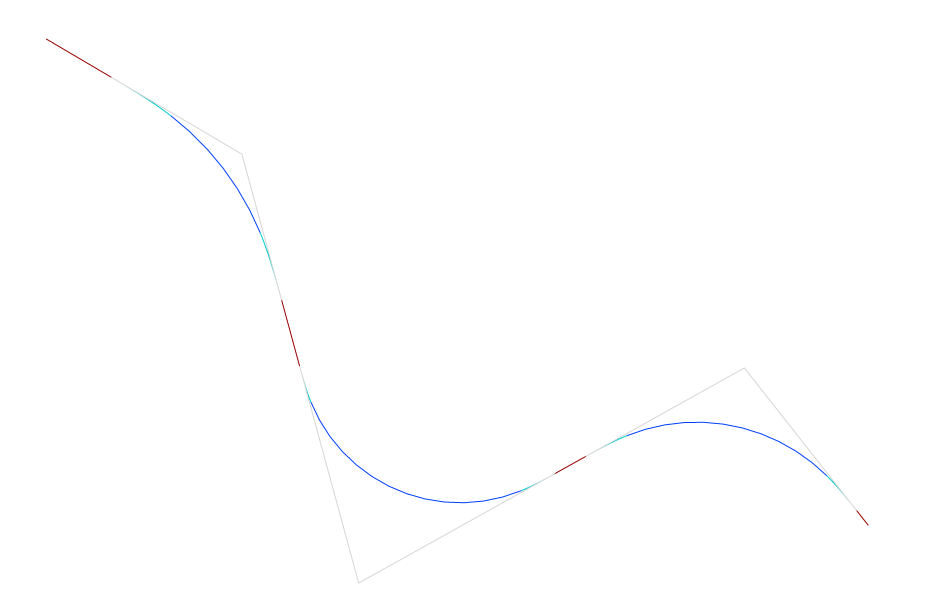
Alignment is a reference system used to position linear objects, like roads, railways, pipe networks, streets, retaining walls and bridges, in space. An alignment is represented with horizontal, vertical 2D curves, resulting in 3D alignment.
- Horizontal alignments
- Horizontal alignment is a 2D curve that is needed to precisely position linear objects in a horizontal direction. It can be created by Points of Intersections (PI), by Alignment Elements, imported from LandXML and from AutoCAD Civil 3D. Horizontal alignment is the horizontal trace on your TIN Surface which is used to generate the elevation profile and vertical alignment. Note: The Horizontal Alignment is not necessarily always projected (draped) on the TIN Surface. Projection is required to create Vertical Alignments and Corridors.
A single horizontal alignment can have one vertical alignment. The horizontal alignment will appear under the surface.
- Vertical alignments
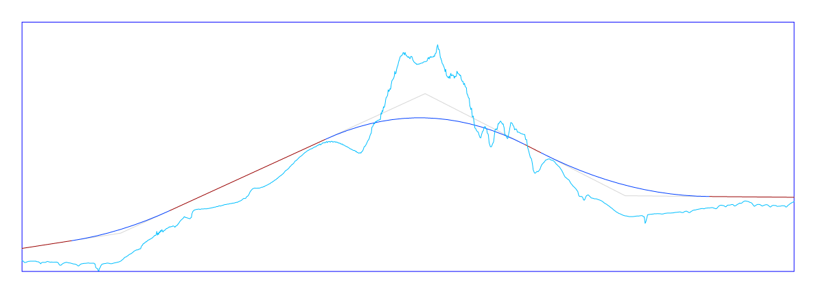
- A vertical alignment is needed to precisely define a linear object in the vertical sense. The horizontal path defined by the horizontal alignment corresponds with a vertical profile of the TIN Surface. By defining Points of Vertical Intersection (PVI) on these vertical profiles of the target surfaces, the new 2D curve defines the vertical alignment.
- 3D alignments
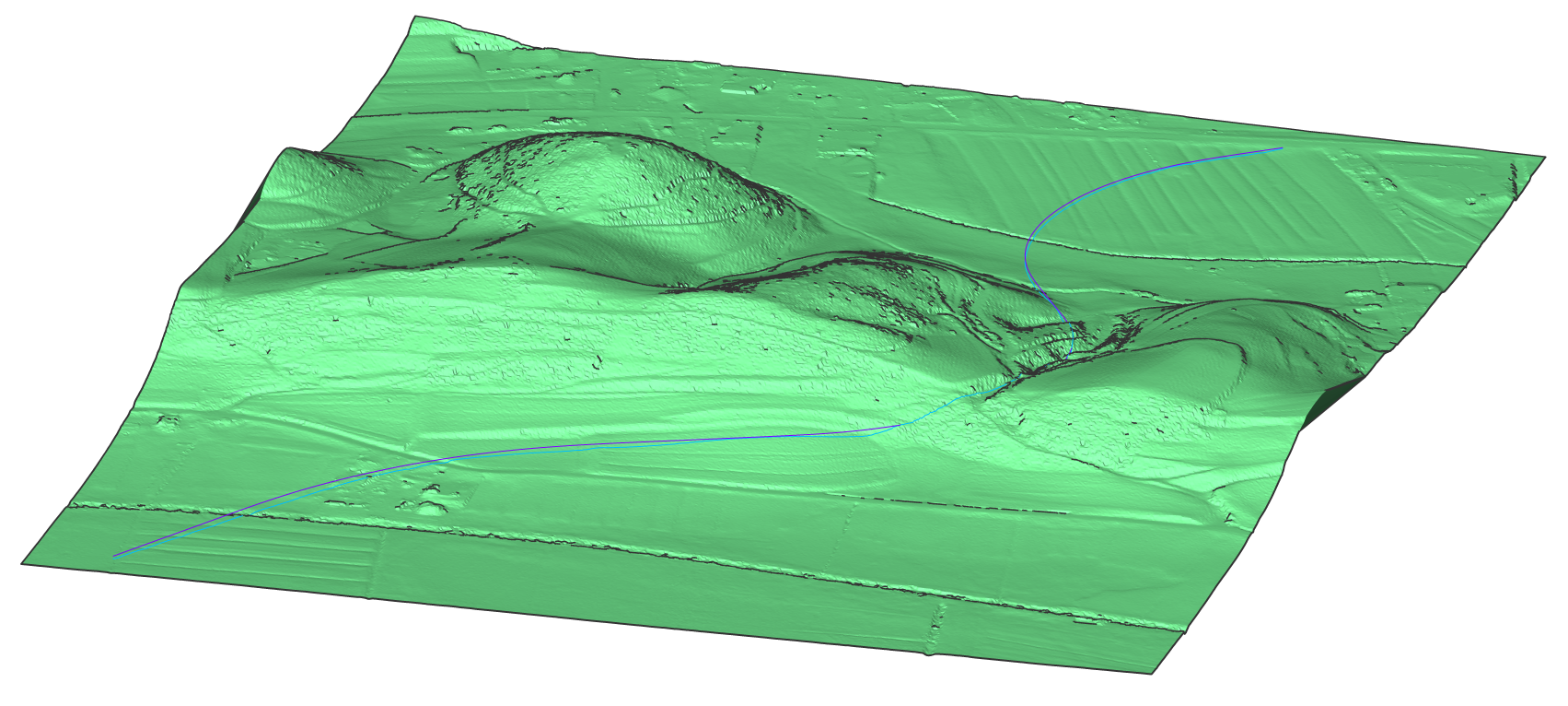
- A 3D Alignment is a 3D polygonal curve defined by the horizontal and vertical alignment.
Procedure: Creating an Alignment by PI
- Open the drawing file that contains a TIN Surface.
- Launch the ALIGNMENT command in the Command line.
- Select the TIN surface.
- Optionally, select the Specify start station option in the Command line to define start station for the alignment
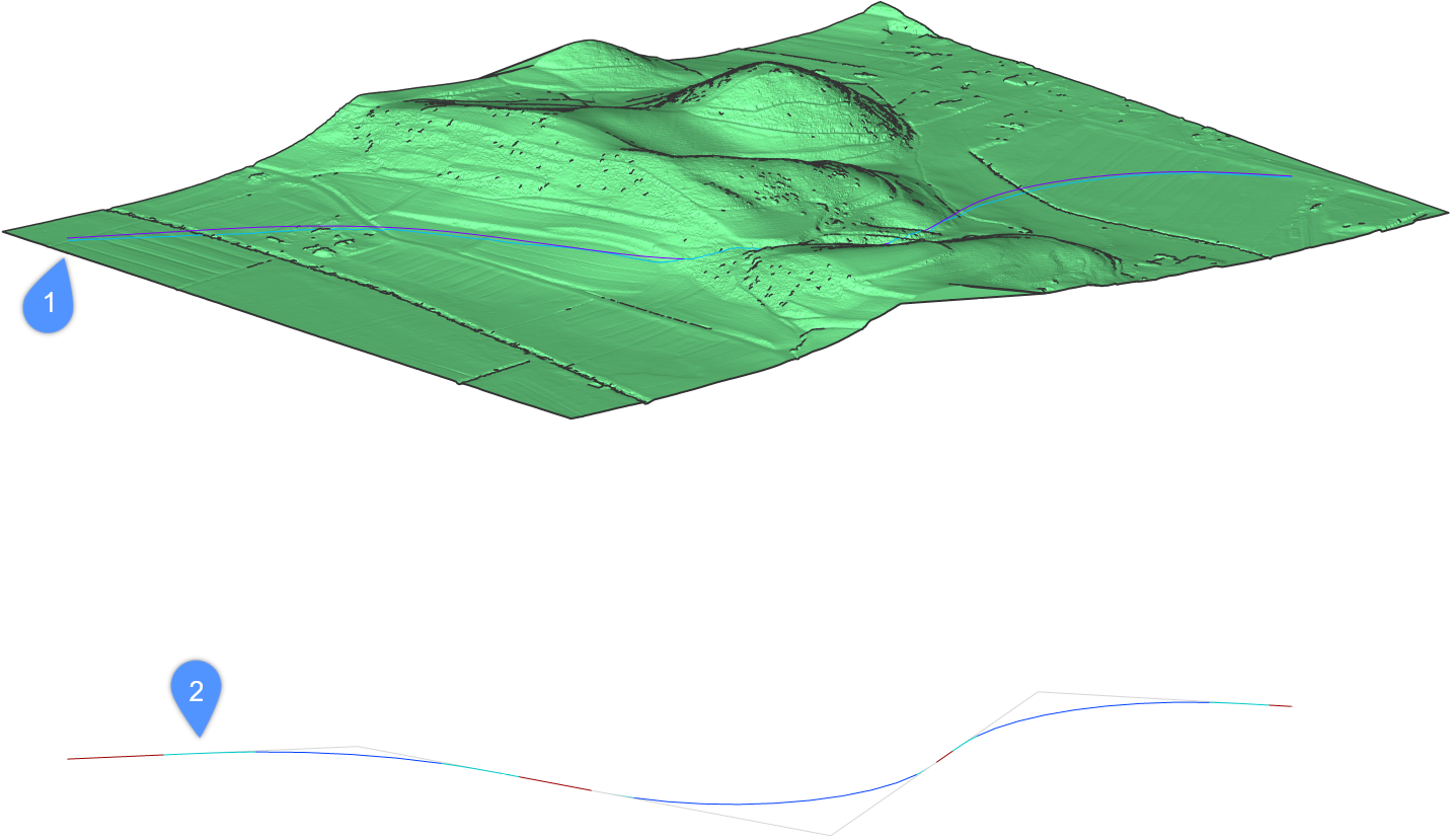
- Pick the horizontal alignment PI points on your surface. Press ENTER when done. Your 3D alignments (1) and horizontal alignment (2) are now generated.
Procedure: Creating a Horizontal Alignment without 3D alignments
- Open a drawing and launch the ALIGNMENT command in the Command line.
- Select the Pick pi point option in the Command line.Note: The Alignment is not projected on the TIN Surface if this option is selected in the Command line.
- Optionally, select the Specify start station option in the Command line to define start station for the alignment
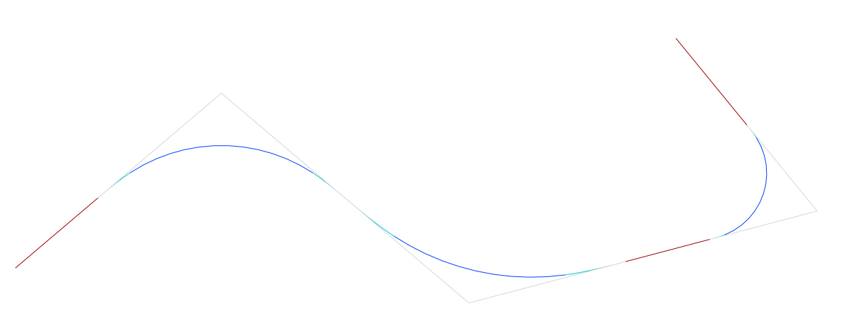
- Pick the horizontal alignment PI points. Press ENTER when done.Your horizontal alignment is now generated.
About Vertical Alignment View
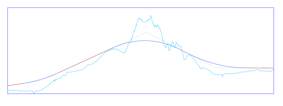
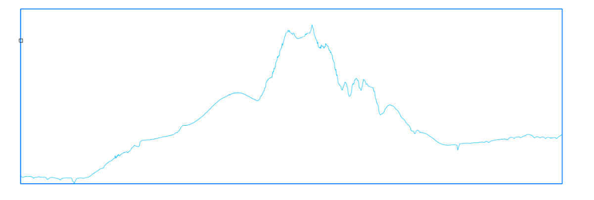
The horizontal alignment creates a vertical section of the target TIN surface. This 2D curve can be displayed in a separate viewport inside your model space using the command ALIGNMENTVIEW.
Creating a Vertical Alignment View
- Open the drawing file that contains a TIN Surface, Horizontal Alignment and 3D Alignments.
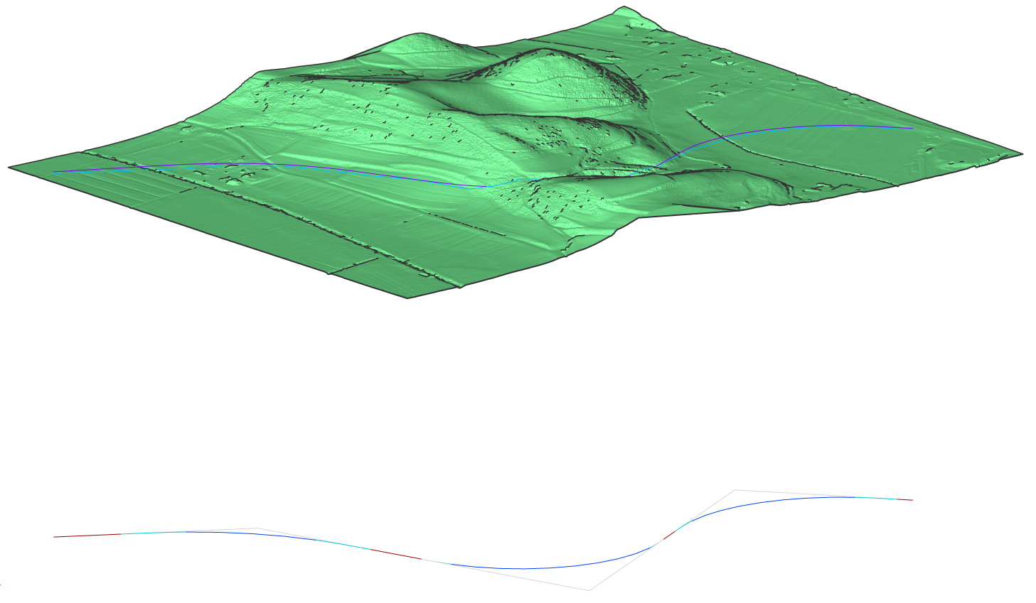
- Launch the ALIGNMENTVIEW command in the Command line.
- Select a horizontal or 3d alignment in the drawing.Note: If you select the Horizontal alignment in a drawing that is not projected yet on TIN Surface, then TIN Surface needs to be selected in the next step.
- Pick a point as origin for the vertical alignment view.
Your vertical alignment view is now generated.
Creating a Vertical Alignment
- Open the drawing file that contains a TIN Surface, Horizontal Alignment and Vertical Alignment View.
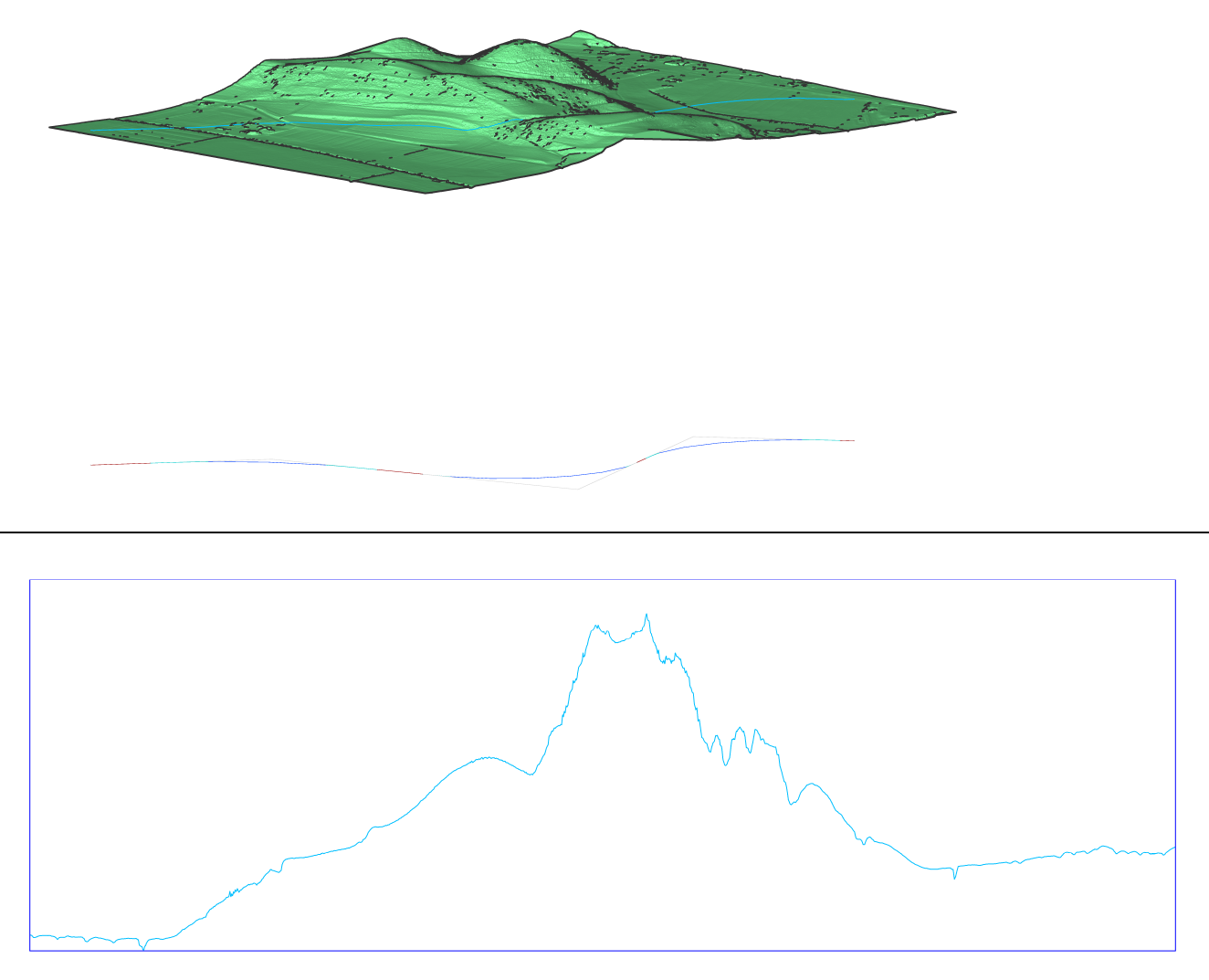
- Launch the ALIGNMENTVERTICAL command in the Command line.
- Select vertical alignment view in the drawing.
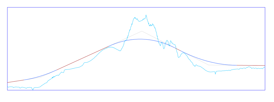
- Pick the vertical alignment PVI points. Press ENTER when done. If you want to go one step back, use Undo. Automatic 3d alignment option generates vertical alignment automatically. Your vertical alignment is now generated.
Attaching new alignment element before or after an existing alignment element
- Draw a new Horizontal alignment using the ALIGNMENTLINE or ALIGNMENTCURVE commands.
- Launch the ALIGNMENTELEMENTFROM command.
You are prompted:
Alignment element [Line/Curve/Spiral/Line with Spiral/Curve with Spiral/Curve-Spiral-Spiral]:
- In the Command line, select which type of element you want to attach. In this example, we will use the Curve with Spiral option.
- You are prompted:
Attach to: [Element/element END]
- Element: select this option to attach new element to the specified point on the attachment element.
- element END: select this option to attach new element to the start/end point of the attachment element.
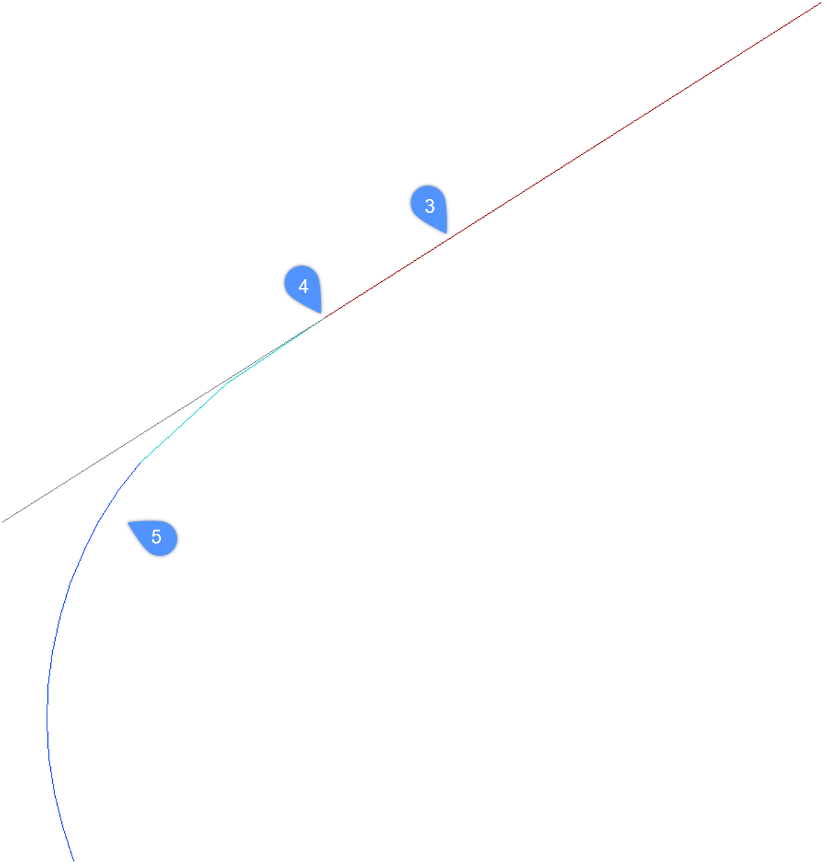
Note: To attach a curve before the existing element, select it closer to the element start point. Otherwise click closer to attachment element end point to attach curve after (starting from) the element. - Select an existing line element (3).
- Specify the spiral radius.
- Specify the spiral length.
- Specify the curve solution angle (greater or less than 180°).
- Specify the curve pass-through point (4) to draw the Curve-Spiral combination (5).Note: The new element is always drawn tangential to the specified point on the selected attachment element.
Attaching new alignment element between two selected alignment elements
- Draw a Horizontal alignment with two elements, using the ALIGNMENTLINE or ALIGNMENTCURVE commands.
- Launch the ALIGNMENTELEMENTBETWEEN command.
You are prompted:
Alignment element [Line/Curve/Spiral/Spiral-Curve-Spiral/Spiral-Spiral/Spiral-Line-Spiral]:
- In the Command line, select which type of element you want to attach. In this example, we will use the Spiral-Curve-Spiral option.
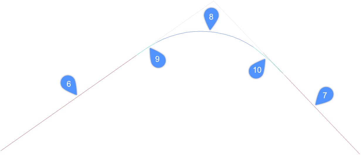
- Select the first attachment element (6).
- Select the second attachment element (7).
- Specify the curve radius (8).
- Specify the spiral in length (9).
- Specify the spiral out length (10).
- The new Spiral-Curve-Spiral combination between the selected alignment elements will be added.Note: The new element is drawn tangential to both attachment elements.
