Compare two models dialog box
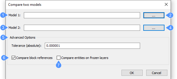
The Compare Two Models dialog box allows you to perform a geometric comparison of solids and surfaces between two drawing files.
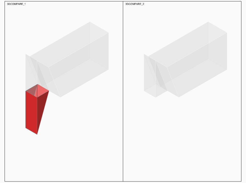
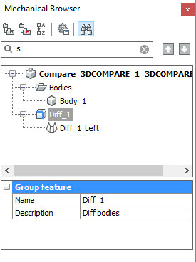
The result is shown in a new drawing and reported in the Mechanical Browser panel.

- Model 1
- Select 1st drawing
- Model 2
- Select 2nd drawing
- Advanced Options
- Compare block reference
- Compare entities on frozen layers
Model 1
Specifies the file name of the first drawing to compare.
Select 1st drawing
Opens the Select first drawing for comparison dialog box to choose the drawing you want.
Model 2
Specifies the file name of the second drawing to compare.
Select 2nd drawing
Opens the Select second drawing for comparison dialog box to choose the drawing you want.
Advanced Options
The tolerance (absolute) expresses the threshold value for geometry comparison: determines how close two models must be to be considered unchanged.
Compare block reference
- Yes - compares solids and surfaces in blocks.
- No - ignores solids and surfaces in blocks.
This command works with regular blocks and inserts of arbitrary depth, which contain solids or surfaces, including assemblies that use block structures.
Compare entities on frozen layers
- Yes - solids and surfaces on frozen layers are compared.
- No - solids and surfaces on frozen layers are ignored.
The value of the 3DCOMPAREMODE system variable controls the display in the viewports of the Comparison layout; in the Settings dialog box, search for "3dcomparemode".
The selected files are attached to a new drawing that is named Compare_<File_1>_<File_2>.dwg
In this drawing, a layout named “Comparison” is created automatically with two viewports, one for each drawing, illustrating the differences between the drawing using colors.

At the same time, the Mechanical Browser panel opens automatically and lists the differences between the 2 drawings.


