AMFCFRAME command
Creates a feature control frame and attaches it to an entity.

Icon: 
Note: This command only works for drawings that contain mechanical entities. To set the environment for BricsCAD Mechanical drawings, see the Overview of 2D Mechanical Drawings commands article.
Description
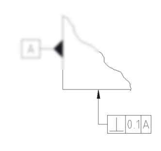
Allows you to create a feature control frame symbol that can be attached to a straight or curved linear entity in the drawing. A feature control frame is rectangular and divided into at least two sections.
Method
Select the entity to attach the feature control frame symbol and specify the points for its location. Press Enter to open the Feature Control Frame dialog box.
Note: The symbol can be placed without a leader and attached line.
Double-click an existing feature control frame symbol to open the Feature Control Frame dialog box to change its properties. You can also configure these properties from the Properties panel.