NEWWIZ command
Opens the Create New Drawing dialog box.

Icon: 
Alias: DDNEW
Description
Opens the Create New Drawing dialog box
The Create New Drawing dialog box allows you to create new drawings by several methods with the New Drawing Wizard.
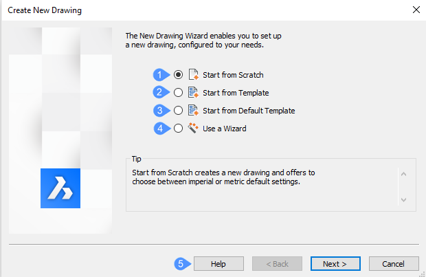
- Start from Scratch
- Start from Template
- Start from Default Template
- Use a Wizard
- Help
Start from Scratch
Starts the new drawing using the default template file specified by the BASEFILE system variable. Click the Next button and choose a measurement system:
- Imperial (feet and inches) - new drawing is based on the default-imperial.dwt file and so uses Imperial measurements.
- Metric - new drawing is based on the default-mm.dwt file and so uses metric measurements.
After you click the Finish button, the program opens a new drawing whose content depends on the default template file.
Start from Template
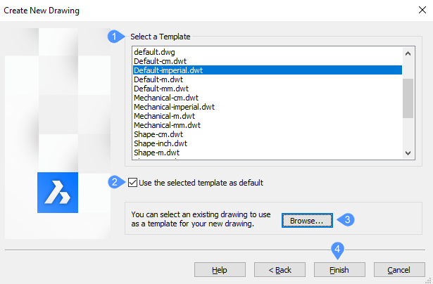
- Select a Template
- Use default template
- Browse…
- Finish
- Select a Template
-
Allows you to choose a file to act as the template. From the Template list, choose one of the DWT file names. These files are stored in the folder specified by the TemplatePath variable; the default location is C:\Users\%username%\AppData\Local\Bricsys\BricsCAD\V26x64\en_US\Templates\.
- Use default template
- Turn on Use the selected template as default option when you want to use this file as the template from now on. If so, then the program updates the value of the BASEFILE system variable. After you click the Finish button, the program opens a new drawing whose content depends on the template file you have selected.
- Browse…
- Opens the Select a template file dialog box from where you can select the following kind of file type for a template: DWG - drawing files, DWT - template files, DXF - drawing interchange files.
- Finish
- Click the Finish button after selecting a Template from the list or from the dialog box.
Start from Default Template
Starts new drawings with the default template defined by the BASEFILE system variable. After you click the Finish button, the program opens a new drawing whose content depends on the template file you have selected.
Use a Wizard
Starts the new drawing by stepping through a wizard that guides you along the way:
- Click the Next button.
- Choose a measurement system:

- Imperial (feet and inches) - new drawing is based on the default-imperial.dwt file and so uses Imperial measurements.
- Metric - new drawing is based on the default-mm.dwt file and so uses metric measurements.
- Click the Next button.
- Select a linear unit of measurement and display precision.
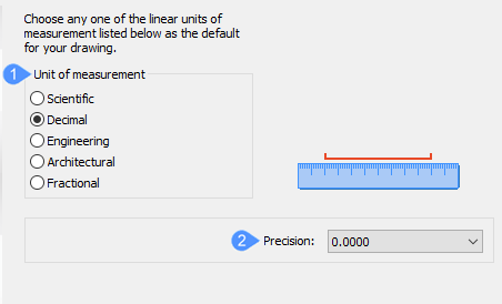
- Unit of Measurement
- Precision
- Unit of Measurement
-
Choose one from the list. If you are unsure, choose Decimal; you can always change the units any time later with the UNITS command.
Unit Name Measures Example Display Architectural Feet, inches, fractional inches 4'-6 1/16" Engineering Feet, inches, decimal inches 4'-6.0625" Fractional Inches, fractional inches 54 1/6" Decimal (default) Units and decimal units 2128.4449 Scientific Units, decimal units, exponents 2.1284E+03
- Precision
-
Click the drop-down list and choose a level of precision. If you are unsure, choose the defaults, as you can always change the precision any time later with the UNITS command.
Note: This is a display precision: the program makes calculations internally always to eight decimal places.Note:- Click the Next button.
- Select an angular unit of measurement and display precision.
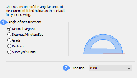
- Angle of measurement
- Precision
- Angle of Measurement
-
Choose one from the list. If you are unsure, choose Decimal/Degrees; you can always change the units any time later with the UNITS command.
Angle Name Measures In Example Decimal degrees Degrees and decimals 12.3456 Degrees/Minutes/Seconds Degrees,minutes,seconds,decimal secs 12d34'56" Grads (g) Grads and decimals 123.45g Radians (r) Radians and decimals 1.23r Surveyor’s Units North/South degrees towards East/West N12d34'56"E
- Precision
-
Click the drop-down list and choose a level of precision. If you are unsure, choose the defaults, as you can always change the precision any time later with the UNITS command.
-
Click the Next button.
- Determine which kinds of plot style the drawing should employ:
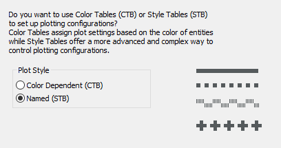
- Color Dependent (CTB) - these plot styles are simpler to employ, but less flexible.
- Named (STB) - plot styles are more flexible, but complex, because they control every aspect of every entity property during plotting.
If you are unsure, choose Color-dependent.
- Click the Next button.
- Choose the default working color, the linetype and the visual aids you want to be displayed by the drawing:
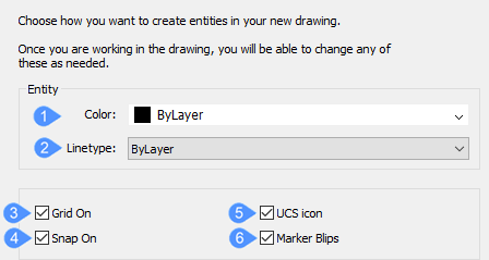
- Color
- Linetype
- Grid On
- Snap On
- UCS icon
- Marker Blips
-
- Color
- You can choose any color from the drop-down list. However, this is not recommended. Choose ByLayer so that layers control the colors of entities. See COLOR and LAYER commands.
- Linetype
- You can choose any linetype from the drop-down list, this again is not recommended. Choose ByLayer, for the same reason. See LINETYPE command.
- Grid On
- When on, displays a grid of dots (or lines) that helps you see the unit spacing, as well as drawing extents, such as every 1m; see the GRID command. It is recommended you turn this on.
- Snap On
- When on, sets the movement increment of the cursor, such as every 0.5m; see SNAP command. It is recommended you turn this on.
- UCS icon
- When on, displays the UCS icon for showing the orientation of the x, y, and z axes; see the UCSICON command. It is recommended that you turn this on for 3D drawings, but turn it off for 2D ones.
- Marker Blips
-
When on, draws a tiny + each time you click in the drawing; see the BLIPMODE command. It is recommended you leave this one off, as it can turn the screen messy.
After you click the Finish button, the program opens a new drawing whose content depends on the default template file and the options you choose during the wizard.
Help
Opens the Bricsys Help article about the NEWWIZ command.

