PROPERTIES command
Opens the Properties panel in Properties mode.

Icon: 
Alias: CH, DDCHPROP, DDMODIFY, MO, PR, PROPS
Description
Opens the Properties panel to display it in the current workspace. The Properties panel appears at the same size and location that it did before it was closed or collapsed. Like any other dockable panel, the Properties panel can be either floating, docked or stacked.
The Properties panel offers a central location to access drawing, viewport, and entity properties.
It can be used in either Properties mode or Quick Select mode.

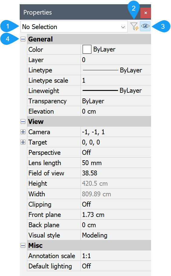
- Entities list
- Switch between Quick Select and Properties
- Property Preview when hovering list values
- Properties list
- Entities list
- Displays the type and number of selected entities.Note: The PROPOBJLIMIT system variable defines the limit of entities displayed in the Properties panel to improve performance. If the number of selected entities exceeds the limit, a warning message appears, and you are allowed to choose one of the options: Ignore limit or Change limit.
- Switch between Quick Select and Properties
- Switches between Properties and Quick Select mode.
- Property Preview when hovering list values
- Turns the PROPERTYPREVIEW setting On or Off.
- Properties list
- Displays relevant property categories based on the current mode and selection set. You can expand and collapse categories by clicking on the + and – icons.
Properties mode
In Properties mode, the Properties panel enables you to view and modify drawing, viewport, and entity properties. Drawing and viewport properties are accessible when the current selection set is empty. Entity properties are accessible when the current selection set has at least one entity.
- Entities list
- When no entities are selected in Properties mode, the entities list shows No Selection and the properties list displays drawing and viewport properties.
- Properties list (no selection set)
- The drawing and viewport properties list, available when no entities are selected, displays General, View, and Misc properties.

- General
- In Properties mode, when no entities are selected, General properties describe the current entity settings. View and modify current entity settings to specify the properties that apply to new entities as they are created. Changing the current entity settings in the Properties list has the same effect as changing the relevant system variables.
- Color
- Describes the current color (CECOLOR system variable). You can specify a new color from the drop-down list or choose Select color to access additional colors from the Color dialog box.
- Layer
- Describes the current layer (CLAYER system variable). You can specify a new layer from the drop-down list.
- Linetype
- Describes the current linetype (CELTYPE system variable). You can specify a new linetype from the drop-down list or choose Load to access additional linetypes from the Load Linetypes dialog box.
- Linetype scale
- Describes the current linetype scale (CELTSCALE system variable). You can enter a new linetype scale.
- Lineweight
- Describes the current lineweight (CELWEIGHT system variable). You can specify a new lineweight from the drop-down list.
- Transparency
- Describes the current transparency level (CETRANSPARENCY system variable). You can specify a new transparency level from the drop-down list or enter a value.
- Elevation
- Describes the elevation relevant to the current UCS (ELEVATION system variable). You can enter a new elevation.
- View
- When no entities are selected, View properties describe the current view and relevant view settings.
- Camera
- Describes the absolute coordinates of the camera in the current UCS, based on the cartesian coordinate system (X,Y,Z). These values automatically update when you orbit or change the viewpoint in other ways.
- Target
- Describes the absolute coordinates of the camera target in the current UCS, based on the cartesian coordinate system (X,Y,Z). These values automatically update when you orbit or change the viewpoint in other ways.
- Perspective
- Describes the current perspective setting (PERSPECTIVE system variable). You can turn Perspective on or off from the drop-down list.
- Lens length
- Describes the current lens length (LENSLENGTH system variable). You can enter a new lens length.
- Field of view
- Describes the current angle for the field of view. You can enter a new angle for the field of view.
- Height (read only)
- Describes the height of the current view.
- Width (read only)
- Describes the width of the current view.
- Clipping
- Describes the clipping mode for the current view. You can specify a new clipping mode from the drop-down list. When clipping is turned on, parts of the view before the front clipping plane and/or behind the back clipping plane are hidden. This property is read only for layouts.
- Front plane
- Describes the location of the front clipping plane. This property is only available when the Clipping property is turned on. This property is read only for layouts.
- Back plane
- Describes the location of the back clipping plane. This property is only available when the Clipping property is turned on. This property is read only for layouts.
- Visual style
- Describes the current visual style of the drawing. You can specify a new visual style from the drop-down list. This property is read only for layouts.
- Misc
- When no entities are selected, Misc properties describe the current annotation scale and default lighting status.
- Annotation scale
- Describes the current annotation scale (CANNOSCALE system variable). You can specify a new annotation scale from the drop-down list.
- Default lighting
- Describes the default lighting status (DEFAULTLIGHTING system variable). You can turn Default lighting On or Off from the drop-down list.
- Properties list (current selection set)
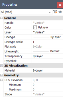
- The Properties list only displays properties that are valid for all the selected or filtered entities. The more types of entities you select, the fewer properties are available on the Properties list. Filtering the entity list enables you to view and modify properties for multiple entities of the same type with minimal effort. When two or more entities are selected, the properties show their common values. Properties that differ between the selected entities are shown as *varies*.Note:
- When area calculations take longer than three seconds, temporary yellowish node labeled "Computing..." is inserted in Properties panel. Even if you interrupt the calculation by pressing ESC in the Properties panel, the entities remain highlighted and their properties are available for the user.
- The mass properties of 3D solids and surfaces are visible in the Properties panel when multiple entities are selected.
All entities display General, 3D Visualization (Model space only), and Geometry properties. Additional properties may display for certain types of entities.

- General Properties
- In Properties mode, when entities are selected, General properties describe properties that are applied to the selected entities and are valid for almost any type of entity. Besides the properties that are available when no entity is selected, there are:
- Handle (read only)
- Describes the unique hexadecimal value by which the selected entity is identified in the DWG database.
- Plot style
- Describes the plot style of the selected entity. You can specify a new plot style from the drop-down list. Note that this property is only available when plot styles are enabled. Also see the PLOTSTYLE command
- Hyperlink
- Describes the URL of the selected entity. You can enter a new URL or choose the Browse button to access the Edit Hyperlink dialog box.
- History
- Enables you to undo editing operations for a selected entity. You can specify a previous step from the drop-down list to undo the entity back to one of the previous steps without undoing all the other commands and view operations that have been executed since. The History property only displays when the selection set includes only one entity.
- Thickness
- Describes the thickness of the selected entity. You can specify a new thickness by entering a value or selecting the picker icon and picking two points in the drawing.
- 3D Visualization Properties
- Describes the materials assigned to the selected entities.
- Material
- Describes the current material of the selected entities. You can specify a new material from the drop-list.
- Geometry Properties
- Describes the geometric characteristics of the selected entities. These properties can vary for different types of entities.
Click the Apply button from the Calculator panel to paste the calculated value in the numeric field from the Properties panel.
Quick Select mode
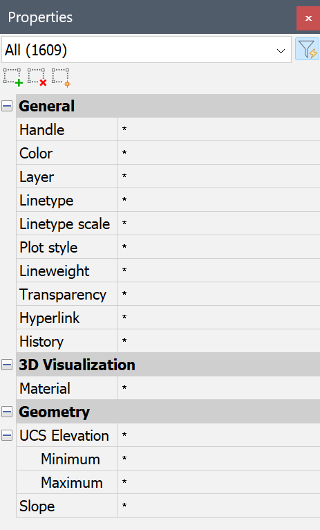
In Quick Select mode, the Properties panel enables you to create a selection set based on entity properties. It includes selection tools and operators.

General procedure:
- Open the Properties panel in the Quick Select mode (1).
- Define an entity type selection set from the Entities drop-down menu (2) for the Quick Select session.
- Filter this selection set by choosing operators and values for entity properties in the Properties list (3).
- Click a selection tool (4) to either:
- add the filtered entity set to the existing selected entities (
 ).
). - remove the filtered entity set from the existing selected entities (
 ).
). - create a new selection set based on the filtered entity set (
 ).
).
- add the filtered entity set to the existing selected entities (
- (Optional) Repeat steps 2 to 4.
For more information, see the Quick select article.

