XATTACH command
Attaches an external referenced file in the current drawing.

Icon: 
Alias: XA
Description
Opens the Select reference file dialog box to select a DWG file to reference to in the current drawing. After selecting the file, click the Open button to display the Attach external reference dialog box. It enables you to specify where and how to attach the DWG file. The attached file will be visible in the Attachments panel.
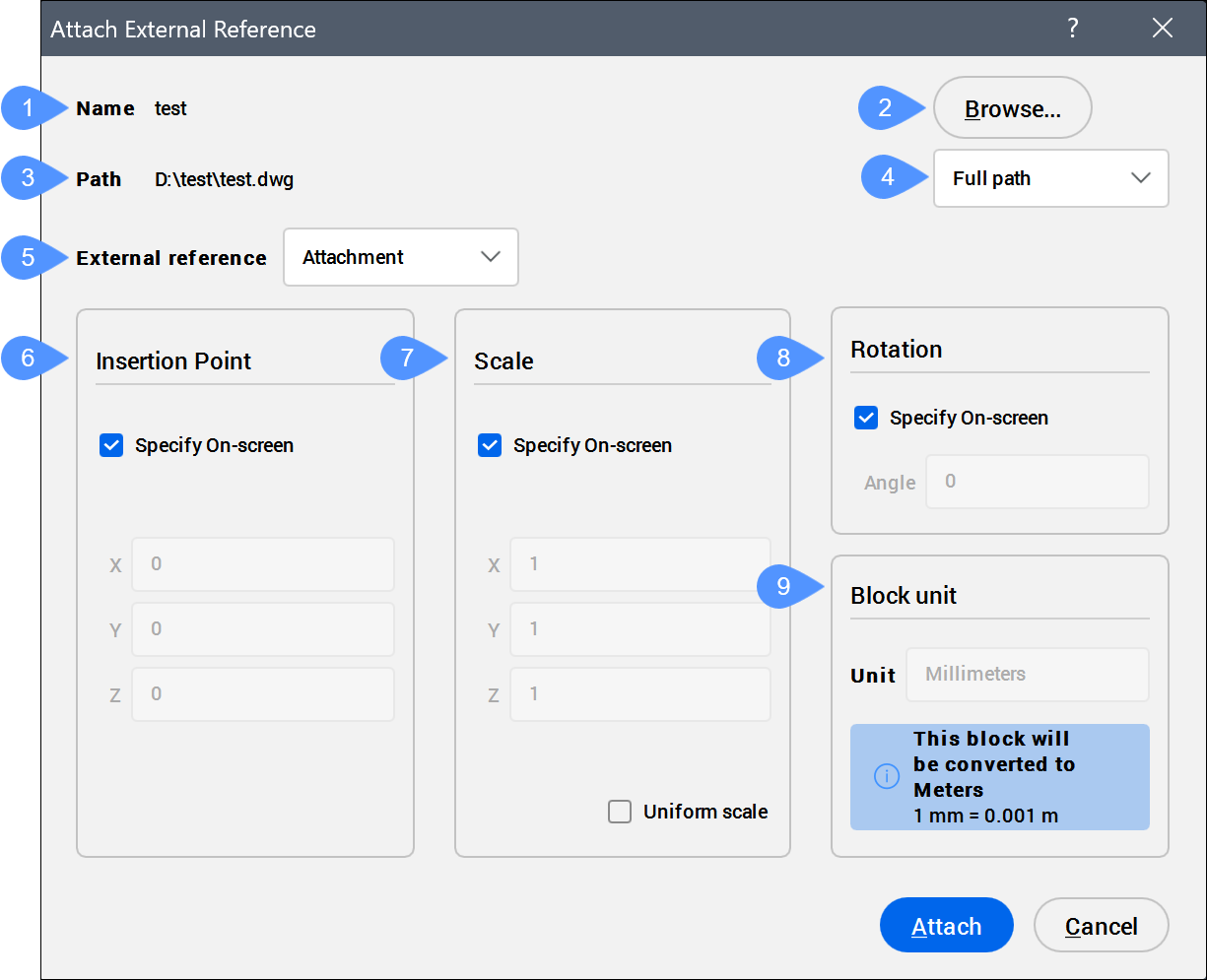
The Attach External Reference dialog box allows you to attach externally referenced drawings to the current drawing.
- Name
- Browse
- Path
- Path type
- External reference
- Insertion Point
- Scale
- Rotation
- Block Unit
Name
Displays the name of the selected DWG file to be attached to the current drawing.
*Varies*, the number of selected blocks appears, and their names are listed.Browse
Opens the Select Reference File dialog box and allows you to choose different DWG files.
Path
Displays the path of the selected drawing file.
*Varies*.Path type
Allows you to choose how the path is stored.
- Full path
- Stores the drive and folder names of the DWG file as an absolute reference, such as c:\cad\dwg\filename.dwg.
- Relative path
- Stores the path from the parent drawing’s location to the referenced drawing's location, such as ..\filename.dwg. The
..refers to the folder above the current one. The drawing must be saved before you can use this option.
- No path
- Strips the drive and folder names, leaving just the DWG file name, such as filename.dwg.
External reference
Allows you to choose the method for attaching the external reference.
- Attachment
- Attaches the Xref and nested Xrefs.
- Overlay
- Attaches only the first level of Xref.
Insertion Point
Specifies the location of the Xrefs lower-left corner.
- Specify On-screen
- Determines how to specify the insertion point.
- On: specify the insertion point in the drawing after the dialog box is closed.
- Off: specify the insertion point in the dialog box using the X, Y, and Z fields.
Note: If multiple DWG files are selected to be attached to the current drawing, the Specify On-screen option is grayed out.
- X, Y, or Z
- Specifies the X, Y, and Z coordinates for the Xrefs insertion point. Use 0,0,0 to insert the Xref at the drawing's origin.
Scale
Specifies the size of the Xref.
- Specify On-screen
- Determines how to specify the scale factors.
- On: specify the scale factors in the drawing after the dialog box is closed.
- Off: specify the scale factors in the dialog box using the X, Y, and Z fields.
- X, Y, or Z
- Specifies the X, Y, and Z scale factors of the Xref in the X, Y, and Z directions. Use 1,1,1 to keep the Xref at its original size.
- Uniform Scale
- Makes the Y and Z scale factors equal to X.
Rotation
Specifies the rotation angle of the Xref.
- Specify On-screen
- Determines how to specify the rotation angle.
- On: specify the angle in the drawing after the dialog box is closed.
- Off: specify the angle in the dialog box using the Angle field.
- Angle
- Specifies the rotation angle about the insertion point. Positive angles rotate the Xref counterclockwise. Negative angles rotate the Xref clockwise. Use 0 to keep the Xref at its original orientation.
Block Unit
Performs the automatic scaling of the block with respect to the INSUNITS and INSUNITSSCALING system variables of the current drawing.