Feature Control Frame dialog box
Opens via: AMFCFRAME command
The Feature Control Frame dialog box allows you to set the symbol for characteristics, their tolerance values, and the letter identifying the datum relative to which the tolerance is specified. Also, it is possible to add notes.
The parameters entered for the feature control frame will be stored temporarily and used as default values for the next feature control frame symbol.
The most recent revision of the standard to which this symbol conforms is displayed at the top of the dialog box.
The dialog box contains two main tabs, Symbol and Leader and text.
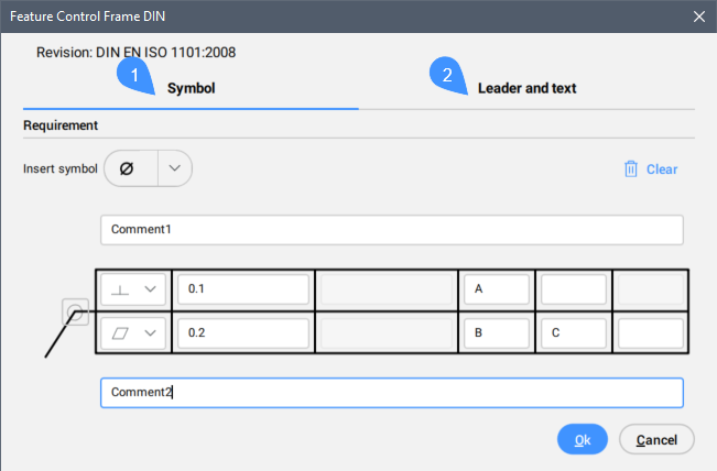
- Symbol
- Leader and text
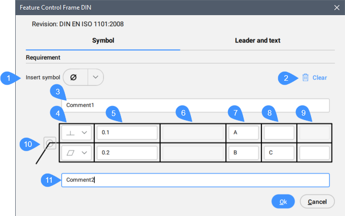
Symbol
Specifies the feature control frame requirements. The drafting standard, ISO, DIN, ANSI, or JIS is written in the Revision field.
- Insert symbol
- Clear
- Top Note
- Geometric symbol
- Tolerance 1
- Tolerance 2
- Datum 1
- Datum 2
- Datum 3
- All around
- Bottom Note
- Insert symbol
- Inserts a symbol from the drop-down list into the selected parameter field.
-

- Clear
- Clears the last inserted parameters. The cells become empty.
- Top Note
- Inserts a note to add above the symbol.
- Geometric Symbol
- Allows you to choose a geometric symbol from the drop-down list.
- Tolerance 1
- Allows you to type in the tolerance to appear next to the geometric symbol.
- Tolerance 2
- Allows you to type in the tolerance to appear next to the geometric symbol.
- Datum 1/2/3
- Allows you to type in additional letters identifying the datum relative to which the tolerance is specified.Note: The second and third fields will become available for writing only after the previous one is filled in.
- All around
- Toggles the visibility of the all around symbol.
- Bottom Note
- Inserts a note to add below the symbol.
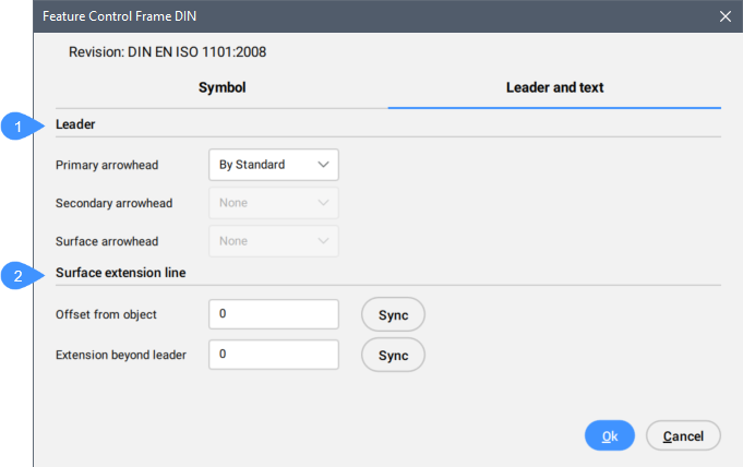
Leader and text
Specifies the Leader and text characteristics.
- Leader
- Surface extension line
- Leader
- Sets the leader characteristics.
- Primary arrowhead
- Defines the default leader arrowhead type from the drop-down list.
- Surface extension line
- Sets the surface extension line characteristics.
- Offset from object
- Defines the distance between the extension line’s start point and the attached object.
- Extension beyond leader
- Defines the distance between the symbol’s start point and the surface extension line’s end point.