Creating roofs
The roof creation workflow consists of the following steps:
- Creating the roof footprint.
- Extrude the footprint and create a hip roof (DMEXTRUDE command).
- Adjust the slope of the roof faces if necessary (Manipulator widget).
- Defining the thickness of the roof solid (Body/Shell option of the SOLIDEDIT command).
- Create additional roof components.
Creating the roof footprint
You can create the roof footprint:
-
From the exterior walls boundary.
-
Creating a closed polyline by clicking points or other 2D procedures.
- Isolate the exterior walls. Isolating entities is easily done using the Structure Panel. See also the ISOLATEOBJECTS command.
- Set the coordinate system to the top face of the exterior walls:
- Type UCS and press Enter.
You are prompted: Specify origin of UCS or [Face/NAmed/Entity/Previous/View/X/Y/Z/Z Axis/Move/World] <World>:
- Snap to a top corner of an exterior wall, then press Enter.
- Type UCS and press Enter.
- Set the Enable boundary detection ON in the Selection Modes toolbar or include the Select detected boundaries into SELECTIONMODES system variable.
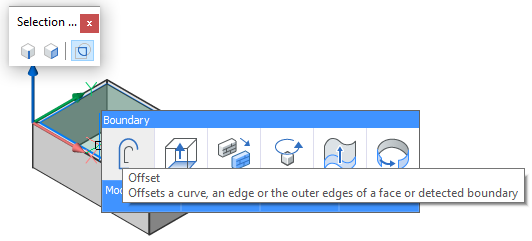
- Move the cursor to avoid area inside the exterior walls.
The inside boundary highlights.
- Choose Offset in the Draw tab of the Quad.
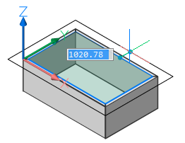
- Do one of the following:
- Type a value in the dynamic distance field.
- Click to accept the value.
Creating a hip roof
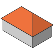
- Create the roof footprint.
- Move the cursor over the roof outline and choose Extrude in the Model tab of the Quad.
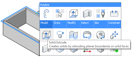
- Move the cursor vertically, then hit the Tab key.
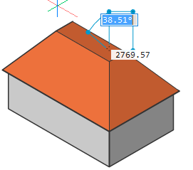
- Type a value in the Taper Angle field and hit the Tab key.
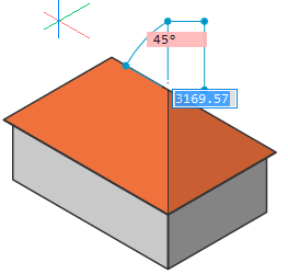
- Do one of the following:
- Hit the Tab key and type another value in the Taper Angle field.
The Taper Angle field is the complement of the inclination angle of the roof.
-
Press Enter to create the roof.
- Hit the Tab key and type another value in the Taper Angle field.
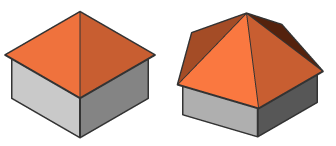
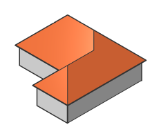
- Depending on the shape of the roof outline, the result is:
- Pyramid roof:
- L-shaped hip roof:
- T-shaped hip roof:
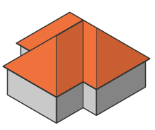
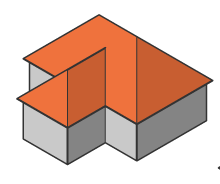
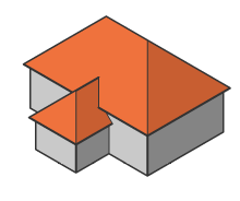
- U-shaped hip roof:
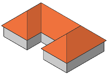
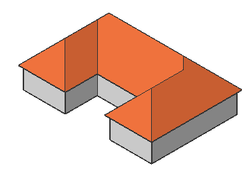
- Complex hip roof:
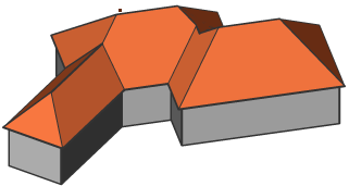
- Pyramid roof:
- To define the thickness of the roof solid we will use the Body/Shell option of the SOLIDEDIT command.Do one of the following:
- Choose Shell in the Solid Edit | 3D Solid Editing ribbon panel.
Or Choose Shell in the 3D Solid Editing toolbar.
- You are prompted: Select 3D solid: Select the roof solid.
- You are prompted: Select face to remove or [Add/Undo/ALL]: Select the bottom face of the roof solid.
- You are prompted: Enter the shell offset distance: Type a value to define the thickness of the roof solid.
- Choose Shell in the Solid Edit | 3D Solid Editing ribbon panel.
Creating a gable roof
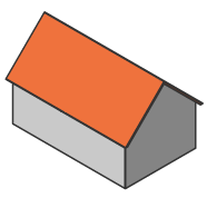
- Create a hip roof.
- Make both end faces vertical:
- Move over the end face then hold down the left mouse button about half a second; the Manipulator widget displays (set the value of the MANIPULATOR system variable = 2).
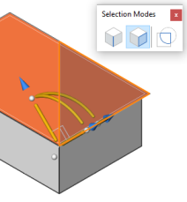
- Place the cursor over the vertical rotation arc. When the arc highlights, move the cursor.
The selected face rotates dynamically.
Click when the face is in a vertical position.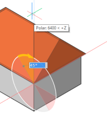
- Move over the end face then hold down the left mouse button about half a second; the Manipulator widget displays (set the value of the MANIPULATOR system variable = 2).
- Execute step 7 of the Create a hip roof procedure. Remove the vertical faces of the roof solid.
Creating a mansard roof
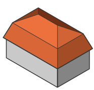
- Create a roof footprint.
- Move the cursor over the roof outline and choose to Extrude in the Model tab of the Quad.

- Move the cursor vertically, then hit the Tab key.
- Type a value in the Taper Angle field then hit the Tab key.The Taper Angle field is the complement of the inclination angle of the roof.
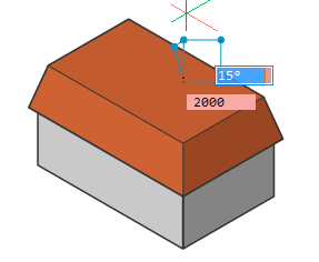
- Type a value in the Extrusion Height field, then do one of the following:
- Hit the Tab key and type another value in the Taper Angle field.
- Press Enter to create the first solid.
- Optionally hit the Tab key to go back and forth between the entry fields and press Enter when you are satisfied with the result.
- Move the cursor of the top face of the first roof solid and choose Extrude in the Quad.
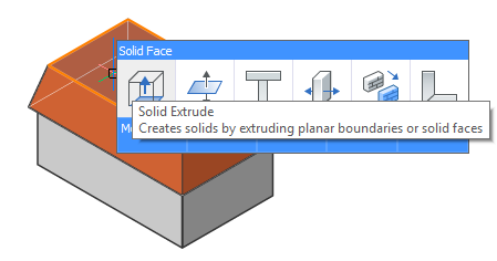
- Move the cursor vertically, then hit the Tab key.
- Type a value in the Taper Angle field then hit the Tab key.
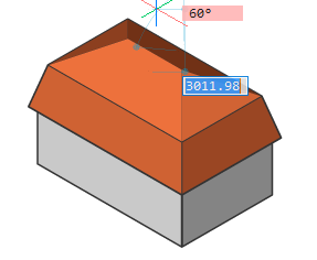
- Do one of the following:
- Hit the Tab key and type another value in the Taper Angle field.
- Press Enter to create the first solid.
- Select both solids and choose Union in the Model tab in the Quad.
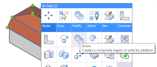
- Repeat step 7 of the Create a hip roof procedure.
Creating a jerkinhead roof
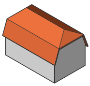
- Execute steps 1 to 6 of Creating a mansard roof procedure, to create the first solid.
- Execute step 2 of Creating a gable roof procedure to set the end faces vertical.
- Execute steps 7 to 11 of the Creating a mansard roof procedure.
- Execute step 7 of the Create a hip roof procedure. Remove the vertical faces of the roof solid.
Creating a gambrel roof
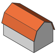
- Execute steps 1 to 6 of Creating a mansard roof procedure, to create the first solid.
- Execute step 2 of Creating a gable roof procedure to set the end faces vertical.
- Execute steps 7 to 10 of Creating a mansard roof procedure to create the second solid.
- Execute step 2 of Creating a gable roof procedure to set the end faces vertical.
- Execute step 11 of Creating a mansard roof procedure.
- Execute step 7 of the Create a hip roof procedure. Remove the vertical faces of the roof solid.
Creating a dutch gable roof
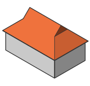
A Dutch gable roof is based on a hip roof.
- Create a hip roof.
- Set the Select Edges option of the SELECTIONMODES system variable ON.
- Move the cursor over the bottom edge of the roof face, then choose Offset in the Draw tab in the Quad.
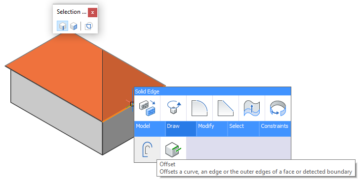
- Move the cursor and type a value in the dynamic distance field or click a point.
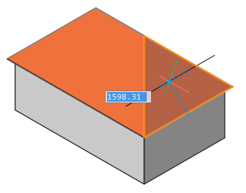
- Do one of the following:
- Choose Imprint in the 3D Solid Editing toolbar.
- Choose Imprint in the Solid Edit | Solid Editing ribbon panel.
- You are prompted: Select 3D solid, surface or region: Select the roof solid.
- You are prompted: Select an entity to imprint: Select the offset roof edge.
- You are prompted: Delete the source object[Yes/No] <No>: Choose Yes.
A triangular face is created.
- Execute step 2 of Creating a gable roof procedure to set the triangular face vertical.
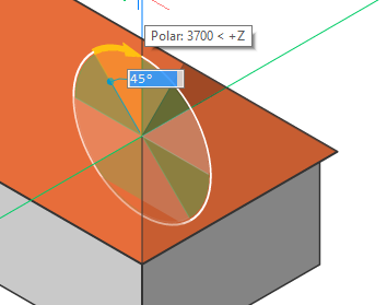
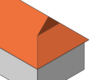
- Execute step 7 of the Create a hip roof procedure to set the thickness of the roof solid.
Creating dormers
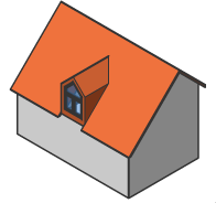
The procedure to create a dormer consists of the following steps:
- Create a box solid at the bottom edge of the roof plane and connect the box to the roof.
- Define the position and dimensions of the dormer.
- Create a dormer roof.
- Right-click, then choose Box in the Model tab of the Quad.
You are prompted: Set corner of box or [Center] <0.00,0.00,0.00>:
- Click a point at the bottom edge of the roof plan.
You are prompted: Set opposite corner or [Cube/Length of side]:
- Click a point, then define the height of the cube: either click a point or type value.
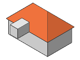
- Select the back face of the cube: move the cursor over the cube at the location of the back face, then hit the Tab key until the face highlights (Selection Modes: Select Faces = ON).
- Choose Connect with nearest in the Model tab in the Quad.
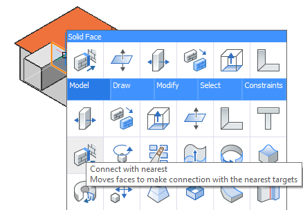
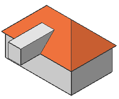
- Select the front face of the box, choose Push/Pull in the Model tab in the Quad and move the face to the roof plane.
- Use PUSHPULL command on the front, top and side face of the dormer solid to define the dimensions and the position of the dormer on the roof:
- Select a side face, then hit the Tab key to define the width.
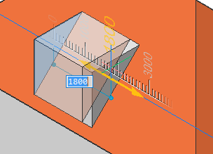
- Select both side faces, then choose to Add rigid set in the Constraints tab in the Quad to fix the width.
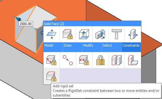
- Drag one of the side faces to position the dormer. Do one of the following:
- Type a distance in the dynamic entry field.
- Click to accept the value.
- Move the cursor over a face that is parallel to the face being dragged and hit the Tab key. The distance field now shows the distance to this face.
- Drag the top face to define the height of the dormer.
- Drag the front face to set the distance from the roof eave.
Move the cursor over the exterior face of the wall beneath the dormer, then hit the Tab key. The distance field now shows the distance to this face.
- Select a side face, then hit the Tab key to define the width.
- Modify the shape of the dormer:
- Add a hip roof.
- Add a hip roof, then rotate the front face vertical to create a gable roof.
- Add a vault.
- Rotate top and side faces.
- Starting from a gable roof move the front face of the dormer backward until the front face is triangular.
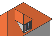
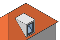
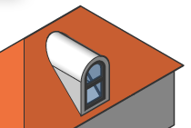
Hip Flat Vault 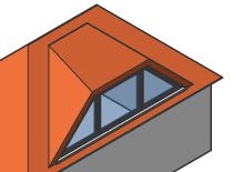
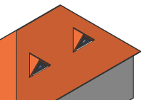
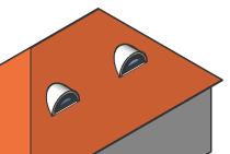
Special Triangle Eyebrow

