Edycja powierzchni TIN
Polecenia
TINEDYTUJPrzegląd
W witrynie BricsCAD® punkty, linie przerwania i granice na powierzchni triangulowanej sieci nieregularnej (TIN) można dodawać lub usuwać za pomocą polecenia TINEDYTUJ.
Następujące jednostki reprezentują cechy na powierzchni TIN:
- Punkty zawierają współrzędne x y i wartości z. Wszystkie punkty są używane do połączenia z dwoma najbliższymi sąsiadami w celu utworzenia trójkątów. Triangulacja powierzchni opiera się na algorytmie Delaunaya, który zapewnia, że żaden punkt nie znajduje się wewnątrz okręgu trójkąta.
- Linie przerywane reprezentują elementy infrastruktury liniowej, takie jak krawężniki, ściany oporowe itp. Linie te definiują również krawędzie trójkątów. Linie łamane mogą być tworzone z elementów liniowych, takich jak linia, polilinia, łuk, okrąg.
- Granice to cechy definiujące ograniczone powierzchnie 3D. Granice powierzchni mogą być tworzone za pomocą zamkniętych polilinii. Zdefiniowanie zewnętrznych granic na dużej powierzchni 3D poprawia wydajność planu powierzchni TIN.
Dodawanie punktów do powierzchni
- Otwórz powierzchnię TIN z punktami powierzchni (1)
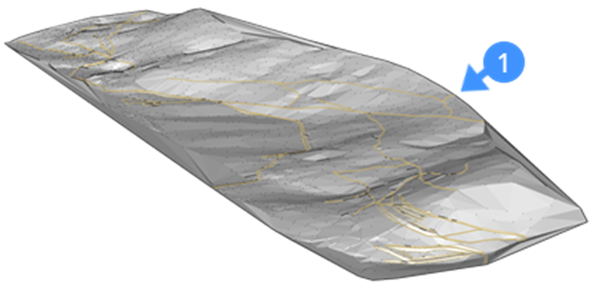
- Wybierz powierzchnię TIN i uruchom polecenie TINEDYTUJ.
- Kliknij obszar, aby dodać punkty do powierzchni.Uwaga:
- Wartość jest obliczana jako interpolowana wysokość dla wybranego punktu wewnątrz trójkąta (2,3,4).
- Jeśli opcja PUNKTY jest włączona, można sprawdzić wysokość punktu we współrzędnych kursora.
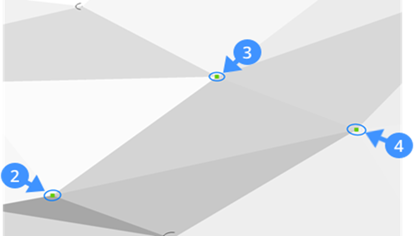
- Aby określić wysokość nowo dodanego punktu, wpisz wartość wysokości w wierszu poleceń i naciśnij klawisz Enter.
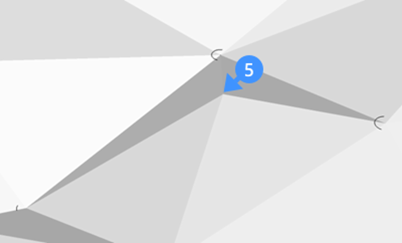
- Kontynuuj dodawanie punktów do powierzchni lub naciśnij Enter, aby wyjść z polecenia. Nowy punkt powierzchni (5) jest dodawany z obiektów, takich jak wierzchołki polilinii.
Dodawanie linii łamanych do powierzchni
- Otwórz powierzchnię TIN (6).
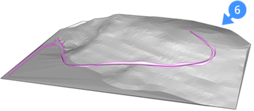
- Wybierz powierzchnię TIN i uruchom polecenie TINEDYTUJ.
- Wybierz Dodaj LinieNieciągłości lub wpisz DL w wierszu poleceń.
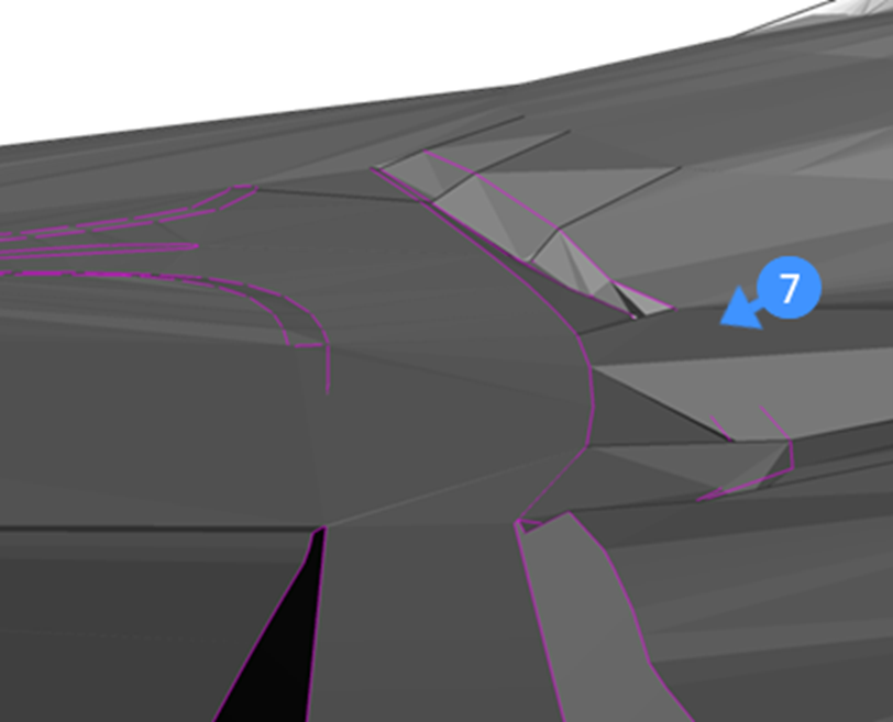
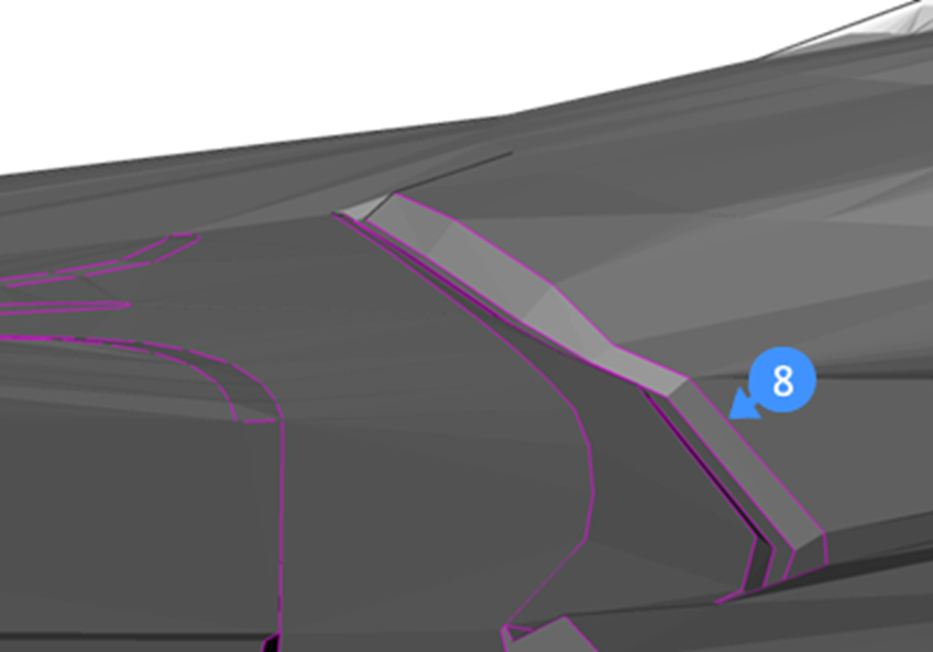
Uwaga: Linie załamania ściany oporowej przed dodaniem linii nieciągłości do powierzchni (7). - Wybierz linie nieciągłości, które chcesz dodać. Spowoduje to zmodyfikowanie powierzchni zgodnie z wybraną linią nieciągłości (8).Uwaga: Jeśli linia przerwania zostanie przesunięta, powierzchnia zostanie zaktualizowana automatycznie.
Dodawanie granic do powierzchni
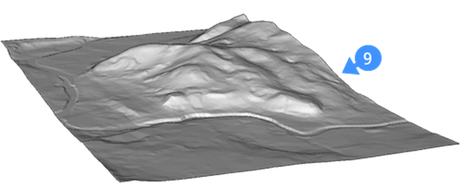
- Otwórz powierzchnię TIN w miejscu, w którym chcesz utworzyć granicę (9).
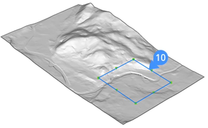
- Utwórz zamkniętą granicę w miejscu, w którym chcesz przyciąć powierzchnię (10).Uwaga: Upewnij się, że funkcja Śledzenie punków charakterystycznych (PUNKTY) jest aktywna.
- Wybierz powierzchnię TIN i uruchom polecenie TINEDYTUJ.
- Wybierz Dodaj Granice w wierszu poleceń.
- Kliknij zamkniętą granicę, aby użyć jej w definicji granicy powierzchni i naciśnij Enter.Uwaga:
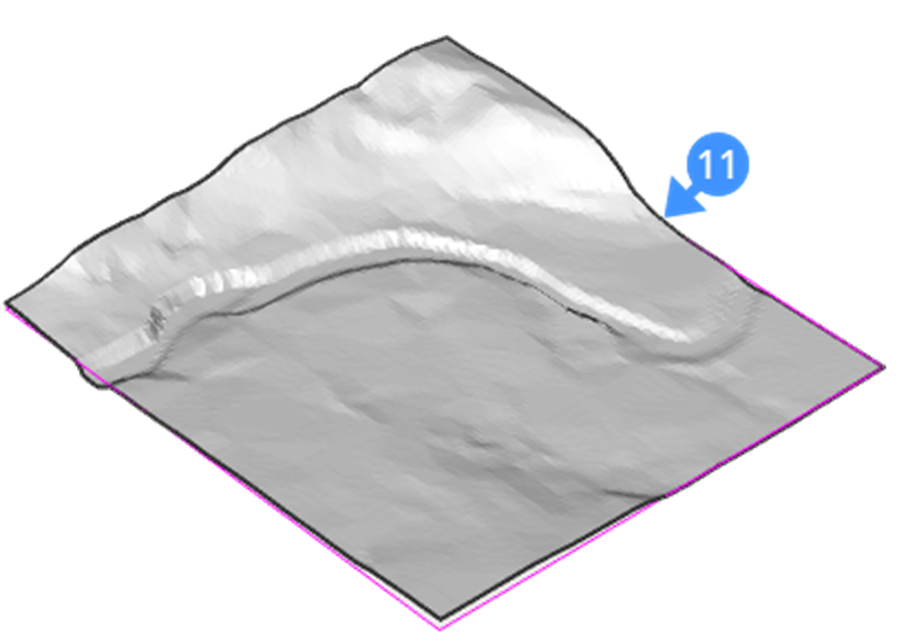
- Domyślnie wybrana jest opcja zewnętrzna, która umożliwia utworzenie zewnętrznej granicy powierzchni (11).
- Wybierz obwiednię (12) (np. polilinie), aby zmienić rozmiar granicy powierzchni. Przesunięcie uchwytu (13) jednostki dynamicznie zmienia powierzchnię (14).

- Wybierz opcję ukrycia, aby wykluczyć część powierzchni z TIN podczas obliczania powierzchni całkowitej.
- Wybierz opcję pokaż, aby ujawnić ukrytą powierzchnię w TIN.
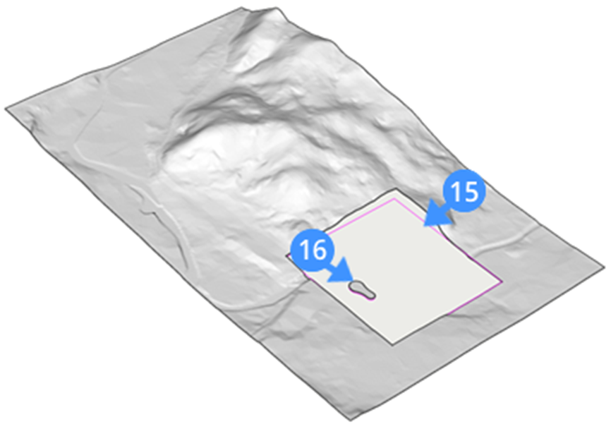
- Ukryta część zgodnie z zamkniętą granicą (15) jest pokazana, a powierzchnia ukrytej części ujawniona (16) za pomocą opcji pokaż.
- Domyślnie wybrana jest opcja zewnętrzna, która umożliwia utworzenie zewnętrznej granicy powierzchni (11).

