ROZMIEŚĆ polecenie
Organizuje przestrzennie zestaw podmiotów poprzez wyrównanie i/lub rozmieszczenie ich wzdłuż osi bieżącego LUW.

Ikona: 
Metody
Polecenie ROZMIEŚĆ organizuje przestrzennie zestaw jednostek (2D i/lub 3D) poprzez wyrównanie i/lub rozmieszczenie ich wzdłuż osi bieżącego układu LUW. Możesz wykonać dowolną liczbę operacji aranżacji na oryginalnym zestawie podmiotów za pomocą jednego uruchomienia polecenia.
To polecenie tworzy nowy układ wybranych podmiotów. Rozmieszczenie podmiotów jest definiowane na podstawie obwiedni wybranych podmiotów (tj. najmniejszej ramki, która zawiera podmiot), w odniesieniu do obwiedni wyboru (tj. najmniejszej ramki, która zawiera wszystkie wybrane podmioty).
Aby utworzyć nowy układ z wybranymi elementami, polecenie ROZMIEŚĆ wykorzystuje następujące elementy:
- Wybór podmiotów (mogą to być zarówno podmioty 2D, jak i 3D).
- Kierunek rozmieszczenia. Może to być oś główna (X, Y lub Z) bieżącego LUW.
- Obwiednia zaznaczenia.
- Pola ograniczające każdej jednostki w zaznaczeniu.
- Opcja rozmieszczenia wybrana przez użytkownika.
Rozmieszczenie wybranych podmiotów odbywa się w następujący sposób:
Aby utworzyć nową konfigurację wybranych podmiotów, polecenie ROZMIEŚĆ wykorzystuje pewne ograniczenia. Po pierwsze, istnieją główne granice, które są dołączone do obwiedni zaznaczenia. Następnie istnieją granice drugorzędne, które są dołączone do obwiedni każdej jednostki w zaznaczeniu.
Jest to prosty przykład obwiedni zaznaczenia i trzech innych obwiedni dla jednostek w zaznaczeniu:
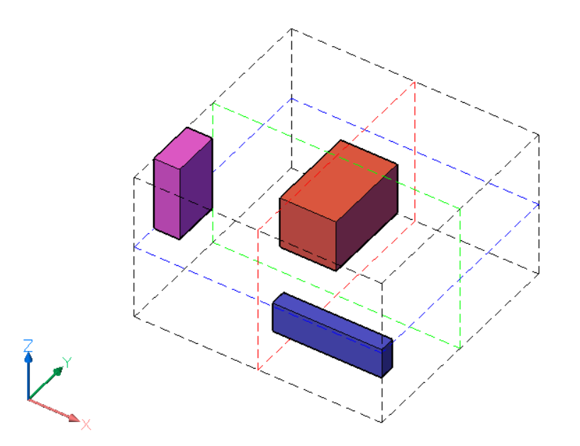
Obwiednia zaznaczenia jest reprezentowana przez czarne przerywane linie. Granice obwiedni zaznaczenia są definiowane przez sześć ścian, po dwie dla każdej osi bieżącego układu LUW. Istnieją również trzy środkowe obwiednie, po jednej dla każdej osi, znajdujące się w środku obwiedni zaznaczenia. Środkowe granice są reprezentowane przez kolorowe przerywane linie, czerwone dla osi X, zielone dla osi Y i niebieskie dla osi Z.
Kolorowe ramki to ramki ograniczające wybranych podmiotów. Dla każdej jednostki w selekcji istnieje sześć granic zewnętrznych, zdefiniowanych przez powierzchnie i trzy granice środkowe. Granice obiektu są zdefiniowane podobnie jak granice pola wyboru.
Podsumowując:
- Wybór podmiotów ma łącznie dziewięć granic. Istnieją trzy granice dla każdej z osi LUW. Notacja tych granic to 1 (Środek), 2 (Dolna) i 3 (Górna) dla każdej z osi.
- Ponadto każda jednostka ma dziewięć granic, podobnych do tych z selekcji.
Dla każdej osi granice są zdefiniowane w następujący sposób:
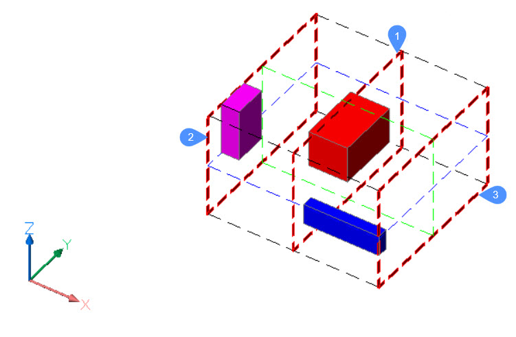
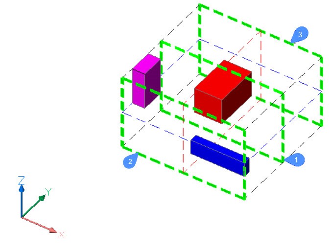
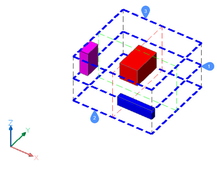
2 - Dolna granica jest definiowana przez powierzchnię obwiedni umieszczoną na najmniejszej współrzędnej wzdłuż określonej osi.
3 - Górna granica jest definiowana przez powierzchnię obwiedni umieszczoną na największej współrzędnej wzdłuż określonej osi.
1 - środkowa granica znajduje się pomiędzy 2 (dolną) i 3 (górną) granicą w tej samej odległości od każdej z nich.
Na poniższych ilustracjach granice obwiedni zaznaczenia zaznaczono grubymi przerywanymi liniami.
Dla osi X:
Dla osi Y:
Dla osi Z:
Aby zdefiniować nową pozycję jednostki w zaznaczeniu, polecenie ROZMIEŚĆ wykorzystuje granice zaznaczenia, granice jednostki i metodę wybraną przez użytkownika.
Panel kontekstowy polecenia Rozmieść
Panel kontekstowy polecenia Rozmieść otwiera się po zakończeniu wybierania podmiotów.
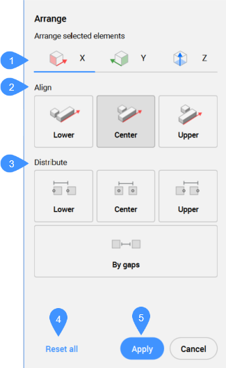
- Kierunek
- Wyrównaj
- Rozprowadź
- Resetuj wszystko
- ZastosujUwaga: Opcje dostępne w tym poleceniu są takie same, jak w panelu kontekstowym polecenia Rozmieść.Uwaga: Wiersz poleceń może być nadal używany do rozmieszczania wybranych elementów, gdy panel kontekstowy polecenia Rozmieść jest aktywny.
Kierunek
Określa kierunek, wzdłuż którego ułożone są jednostki. Możliwe kierunki to trzy główne osie LUW.
- Kierunek X
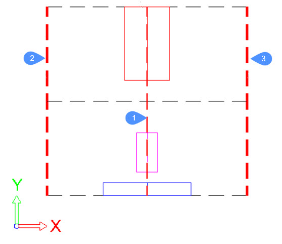
- Jako przykład, jest to uproszczony widok 2D, w płaszczyźnie XY, sytuacji opisanej powyżej:
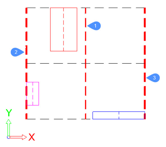
Główne granice, dołączone do ramki ograniczającej zaznaczenie, są reprezentowane przez grube przerywane czerwone linie.
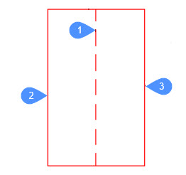
Dla każdej jednostki w zaznaczeniu, jej obwiednia jest reprezentowana przez ciągłe linie, każda w innym kolorze. W tym przypadku dla każdej jednostki granice, 2 (dolna), 1 (środkowa) i 3 (górna), będą odpowiednio lewą stroną, środkową linią i prawą stroną jej prostokąta ograniczającego.
W przypadku czerwonej jednostki granice będą wyglądać następująco:
- Kierunek Y
- Granice są definiowane w podobny sposób jak w kierunku X.
- Kierunek Z
- Granice są definiowane w podobny sposób jak w kierunku X.
Wyrównaj
- Żaden
- Podmioty nie zostaną ułożone wzdłuż określonego kierunku. Jeśli układ został już ustawiony wzdłuż określonego kierunku podczas wykonywania polecenia, jednostka zostanie przesunięta do pierwotnej pozycji na określonej osi.
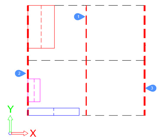
- Dolne wyrównanie
- Dolna granica każdej jednostki zostanie wyrównana z dolną granicą obwiedni zaznaczenia w określonym kierunku.
- Wyrównanie do środka
- Środkowe obramowanie każdej jednostki zostanie wyrównane ze środkowym obramowaniem pola wyboru w określonym kierunku.
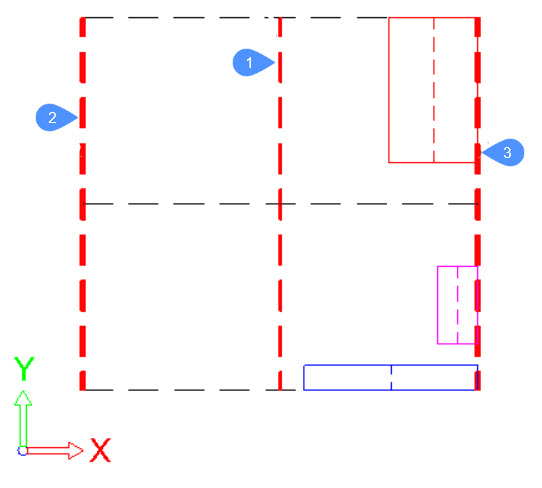
- Górne wyrównanie
- Dolna granica każdej jednostki zostanie wyrównana z dolną granicą obwiedni zaznaczenia w określonym kierunku.
Rozprowadź
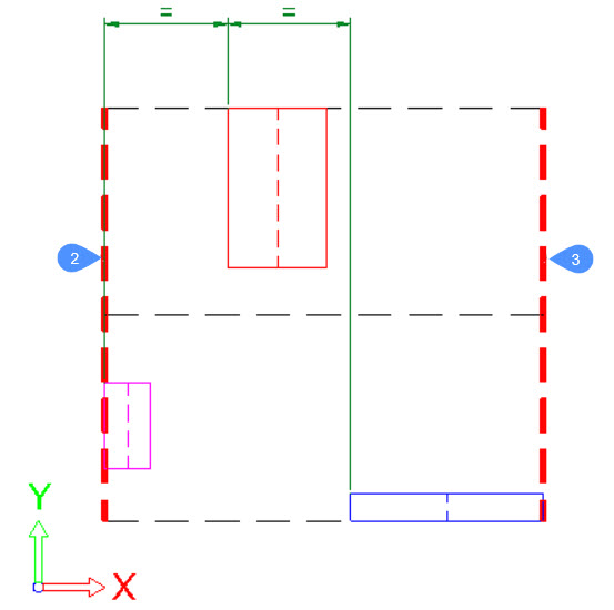
- Niżej (w równych odstępach)
- Odległość między dolnymi granicami kolejnych jednostek będzie taka sama wzdłuż określonego kierunku.
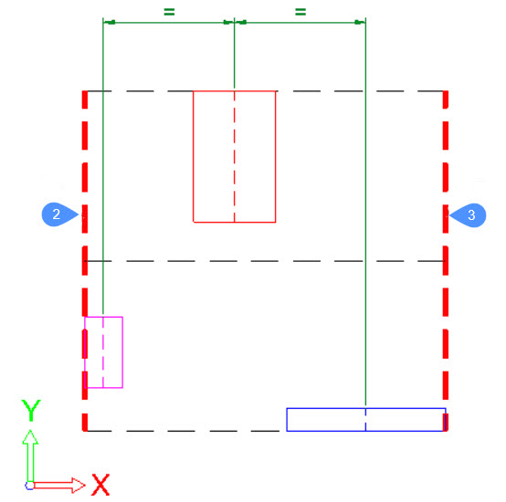
- Środek (w równych odstępach)
- Odległość między środkowymi granicami kolejnych jednostek będzie taka sama wzdłuż określonego kierunku.
- Górne (równomiernie rozmieszczone)
- Odległość między dolnymi granicami kolejnych jednostek będzie taka sama wzdłuż określonego kierunku.
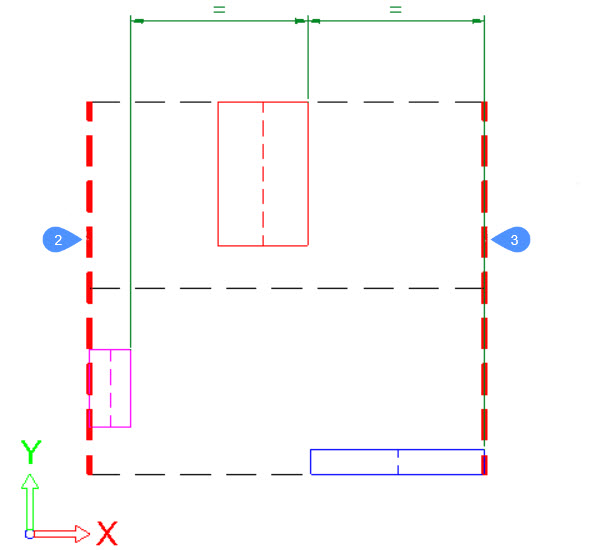
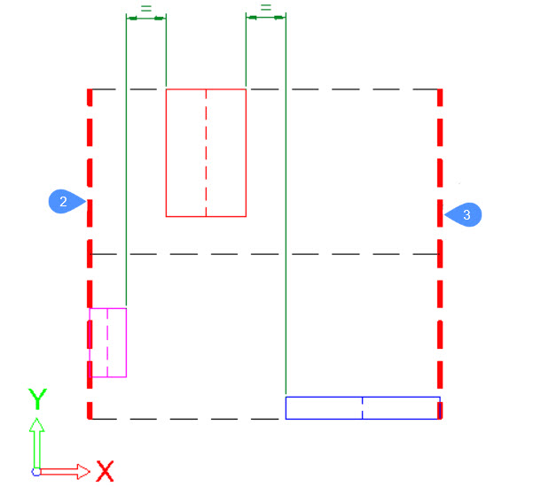
- Przez luki/równomiernie rozmieszczone
- Odległość między dolnymi granicami kolejnych jednostek będzie taka sama wzdłuż określonego kierunku.
Resetuj wszystko
Resetuje wszystkie jednostki do ich początkowej pozycji sprzed uruchomienia polecenia.
Zastosuj
Stosuje zmianę układu i zamyka polecenie.

